
A kind of construction steel beam drilling device

A drilling device and construction steel technology, applied in the field of construction steel beams, can solve the problems of reducing the service life of steel beams, low efficiency, affecting the assembly and installation of steel beams, etc., to achieve the effects of improving accuracy, ensuring continuity, and improving efficiency

Inactive Publication Date: 2020-10-13
THE FIRST CONSTR ENG COMPANY LTD OF CHINA CONSTR SECOND ENG BUREAU
View PDF7 Cites 0 Cited by
  • Summary
  • Abstract
  • Description
  • Claims
  • Application Information

AI Technical Summary

Problems solved by technology

However, since the shape of the hole on the steel beam is not a simple round hole, but a long strip, it greatly increases the difficulty of manual drilling with an electric drill.
At the same time, the accuracy of drilling is low, which will not only affect the normal assembly and installation of steel beams, but also reduce the service life of steel beams
In addition, the existing drilling device cannot automatically and continuously drill holes, resulting in low efficiency

Method used


Image

  • A kind of construction steel beam drilling device
  • A kind of construction steel beam drilling device
  • A kind of construction steel beam drilling device

Examples


Embodiment Construction

[0018] All features disclosed in this specification, or steps in all methods or processes disclosed, may be combined in any manner, except for mutually exclusive features and / or steps.

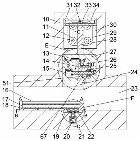
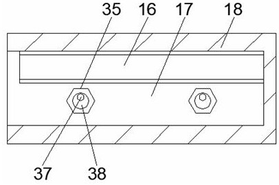
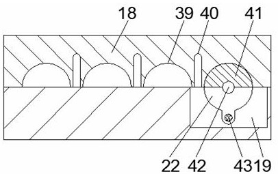
[0019] Combine below Figure 1-7 The present invention is described in detail, and for convenience of description, the orientations mentioned below are now stipulated as follows: figure 1 The up, down, left, right, front and back directions of the projection relationship itself are the same.

[0020] A construction steel beam drilling device of the device of the present invention comprises a body 10, a reciprocating chamber 30 is provided in the body 10, and a reciprocating mechanism for driving continuous drilling of steel beams is provided in the reciprocating chamber 30, the reciprocating A riser chamber 24 is provided below the cavity 30, and a working block 27 is slidably arranged in the riser chamber 24. A transmission groove 13 is provided in the work block 27. A rectangular groove 15 ...


PUM


Abstract

The invention discloses a drilling device for a building steel girder. The drilling device for the building steel girder comprises a device body. A reciprocating cavity is formed in the middle of thedevice body, and a reciprocating mechanism is arranged in the reciprocating cavity. A rising cavity is formed below the reciprocating cavity. A working block is slidably arranged in the rising cavity.A transmission groove is formed in the working block. A rectangular groove is formed below the transmission groove. A moving groove is formed in the right side of the rectangular groove. A drilling mechanism is arranged in the moving groove. A stroke groove which communicates with the moving groove and is open downwards is formed below the moving groove. A driving mechanism is arranged outside the moving groove. A working cavity which communicates with the rising cavity and is through in the left-right direction is formed below the rising cavity. A positioning mechanism is arranged in the working cavity. An intermittent cavity communicating with the working cavity is formed below the working cavity. A connecting cavity is formed below the intermittent cavity. An intermittent feeding mechanism is arranged between the intermittent cavity and the connecting cavity.

Description

technical field [0001] The invention relates to the technical field of building steel beams, in particular to a drilling device for building steel beams. Background technique [0002] Steel beams are a common building component made of hot-rolled I-beams or channel steels, etc. Prior to assembly and installation, drilling operations are required on the steel beams. At present, a common drilling device is performed by an electric drill. But, because the shape of the hole on the steel beam is not a simple circular hole, but a long strip, it greatly increases the difficulty of manual drilling with an electric drill. At the same time, the accuracy of drilling is low, which will not only affect the normal assembly and installation of the steel beam, but also reduce the service life of the steel beam. In addition, the existing drilling device cannot drill holes automatically and continuously, resulting in low efficiency. Contents of the invention [0003] Aiming at the defic...

Claims


Application Information

Patent Timeline
Patent Type & Authority Patents(China)
IPC IPC(8): B23B41/00B23B47/20B23Q3/06
CPCB23B41/00B23Q3/06B23Q5/28
Inventor 戴凤
Owner THE FIRST CONSTR ENG COMPANY LTD OF CHINA CONSTR SECOND ENG BUREAU
Learn More