Massage machine
A technology of massage part and adjustment mechanism, applied in the direction of roller massage, vibration massage, kneading massage appliances, etc., can solve the problems of user's feeling of yielding, discomfort, difficulty in movement, etc., and achieve a simple structure and prevent the feeling of yielding. Effect
- Summary
- Abstract
- Description
- Claims
- Application Information
AI Technical Summary
Problems solved by technology
Method used
Image
Examples
no. 1 Embodiment approach
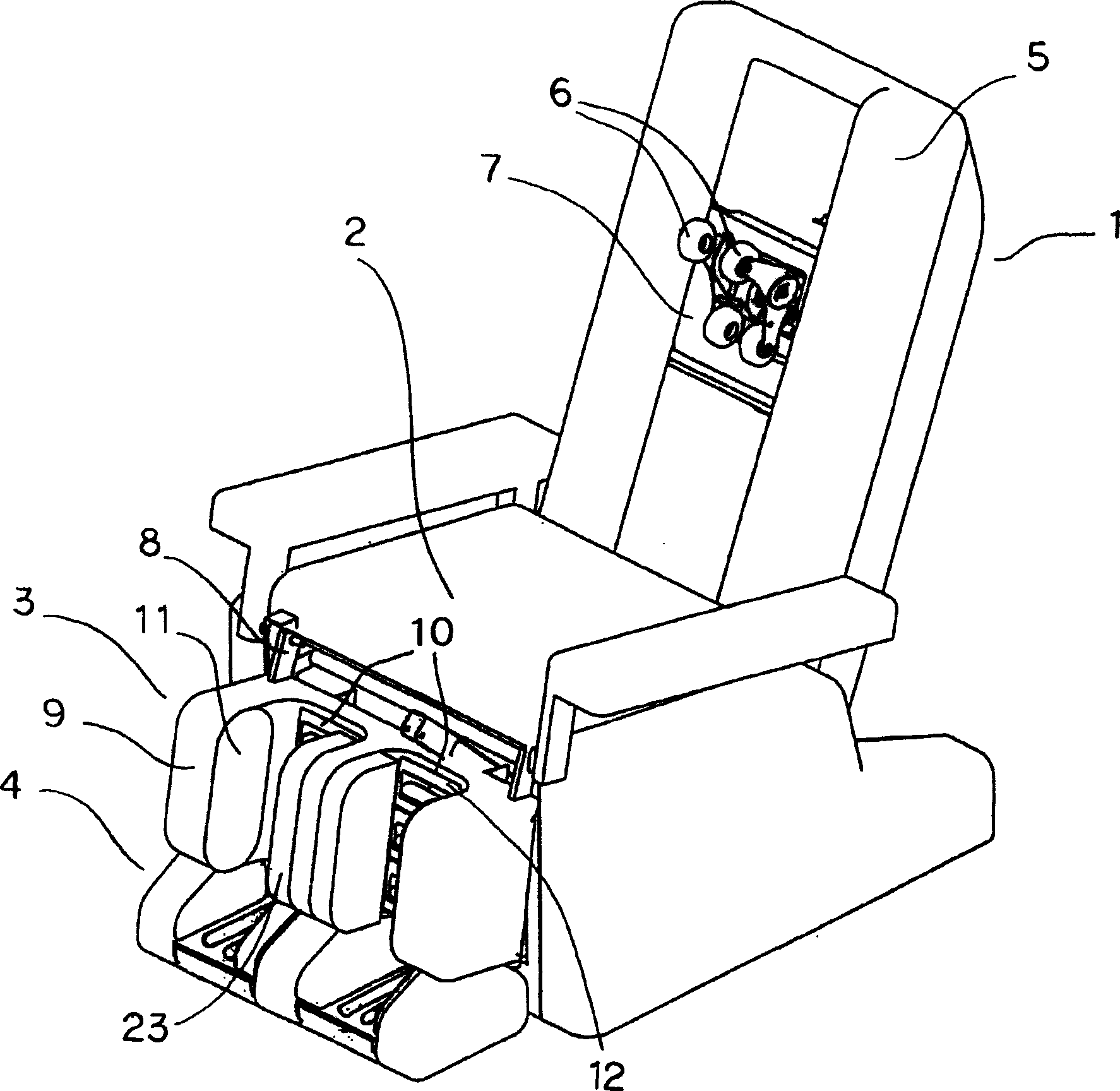
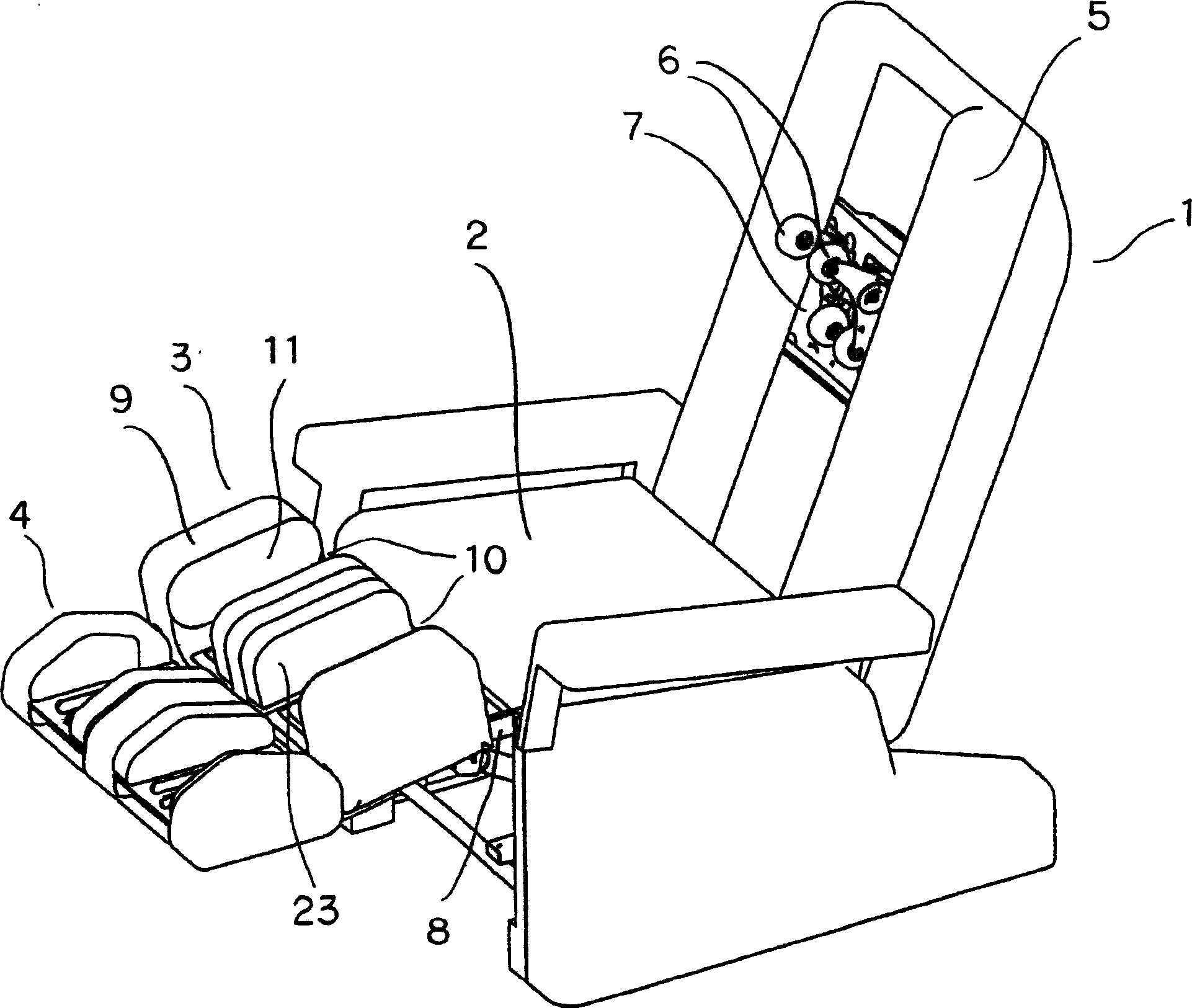
[0031] The following is based on Figure 1 to Figure 6 The massage chair of the first embodiment will be described in detail. Such as figure 1 As shown, a leg massage unit 3 is provided in front of the seat part 2 of the massage chair 1 , and a toe massage unit 4 implementing the structure of the massage machine 1 of the present invention is provided below the leg massage unit 3 . As the massage chair 1, well-known massage chairs can be used.
[0032] For example, as massage chair 1, such as figure 1 as well as figure 2 As shown, a massage chair in which a massage mechanism 7 having a pair of left and right massage balls 6 is disposed on the backrest 5 of the chair can be exemplified. The massage mechanism 7 can move up and down along the backrest part 5, and both can make the massage balls 6 approach each other and leave to perform a kneading massage on the person being massaged, and can swing up and down to perform a beating massage. The backrest part 5 is covered by a...
no. 2 Embodiment approach
[0045] Figure 7 ~ Figure 10 The second embodiment of the present invention is shown. In addition, the same code|symbol is attached|subjected to the same member as 1st Embodiment, and the description is abbreviate|omitted. A motor 33 is disposed at the center of the frame 27 , and its output shaft 34 is connected to a pulley 36 via a belt 35 . A shaft 37 is pressed into the center of the pulley 36, and the shaft 37 rotates together with the pulley 36. Both ends of the shaft 37 are rotatably supported by substantially U-shaped support members 38 disposed on the frame 27 . Such as Figure 10 As shown, a substantially cylindrical cam 39 is fixed to the shaft 37 inside the support member 38 , and the fixed position is offset from the center of the cam 39 . The massage head 40 is placed between the cam 39 and the supporting member 38 so as to be able to move up and down.
[0046] Driven by the motor 33 , the shaft 37 rotates via the output shaft 34 , the transmission belt 35 ,...
no. 3 Embodiment approach
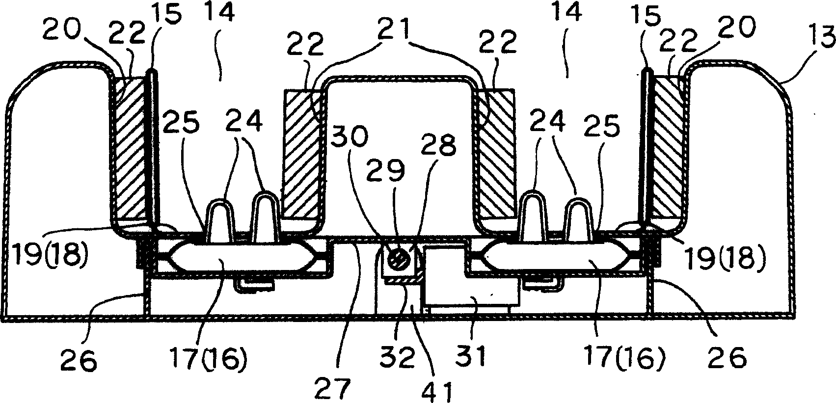
[0048] Figure 11 to Figure 13 The third embodiment of the present invention is shown. In addition, the same code|symbol is attached|subjected to the same member as 1st Embodiment and 2nd Embodiment, and the description is abbreviate|omitted. In the third embodiment, side airbags 15 are disposed on both side walls of the concave receiving portion 14 . With this structure, the position of the foot F relative to the massage head 24 can be freely adjusted. For example, make Figure 11 If such left and right side airbags 15 are inflated evenly, since the massage head 24 is located in the approximately middle of the sole of the foot, the approximately middle sole of the foot can be massaged emphatically. only make Figure 12 When the side airbag 15 on the inner side of such concave receiving part 14 inflates, since the massage head 24 is positioned on the inner sole, the inner sole can be massaged emphatically. only make Figure 13 When the side airbag 15 on the outer side of...
PUM
 Abstract
Description
Claims
Application Information
 - R&D
- Intellectual Property
- Life Sciences
- Materials
- Tech Scout
- Unparalleled Data Quality
- Higher Quality Content
- 60% Fewer Hallucinations
Browse by: Latest US Patents, China's latest patents, Technical Efficacy Thesaurus, Application Domain, Technology Topic, Popular Technical Reports.
© 2025 PatSnap. All rights reserved.Legal|Privacy policy|Modern Slavery Act Transparency Statement|Sitemap|About US| Contact US: help@patsnap.com


