
Floating connector

A floating connector and connector technology, which is applied in the direction of connection, two-part connection device, and parts of the connection device, can solve the problems of increased resistance, poor workability, and difficulty in absorbing deviation, and achieves absorption of relative position deviation, The effect of strong self-reliance and simple manufacture

Inactive Publication Date: 2005-02-16
JST MFG CO LTD
View PDF2 Cites 14 Cited by
  • Summary
  • Abstract
  • Description
  • Claims
  • Application Information

AI Technical Summary

Problems solved by technology

For this reason, when a strong tensile force is applied to the base insulator and the guide insulator in the mating direction of the connector on the opposite side, the mating force with the positioning step of the first mating piece will reach a critical value. , so that the base insulator and the guide insulator are likely to be separated
[0007] In addition, in the case of manufacturing such a connector device, since it is necessary to fit a pair of first engaging pieces of the base insulator to the positioning step portion of the guide insulator, and to press the contact holding portion into the base insulator In the first receiving part of the guide insulator, and the middle part of the contact is stored in the second receiving part of the guide insulator, so the operation is complicated
Moreover, if the matching positions of the first matching piece and the positioning step are disordered, the first receiving portion and the second receiving portion are inconsistent, so in order to make them consistent, the first matching piece must be bent and inserted into the contact receiving portion. The work in the middle, so the workability is poor
[0008] Moreover, since the floating part of the contact is in the shape of a plate, when the floating part is bent in its thickness direction, it is easy to absorb the deviation in the position relative to the connector on the opposite side because the floating part is bent in the direction of its thickness. When the resistance becomes larger, it is difficult to absorb the deviation
Moreover, since the middle part of the contact is accommodated only in the receiving part of the guide insulator, once the floating part bends, the contact part is likely to move relative to the guide insulator
In this way, poor contact may occur between the contact part of the contact and the contact on the opposite side, and the contact part of the contact contacts the connector on the opposite side, causing buckling

Method used


Image

  • Floating connector
  • Floating connector
  • Floating connector

Examples


Embodiment Construction

[0033] specific implementation

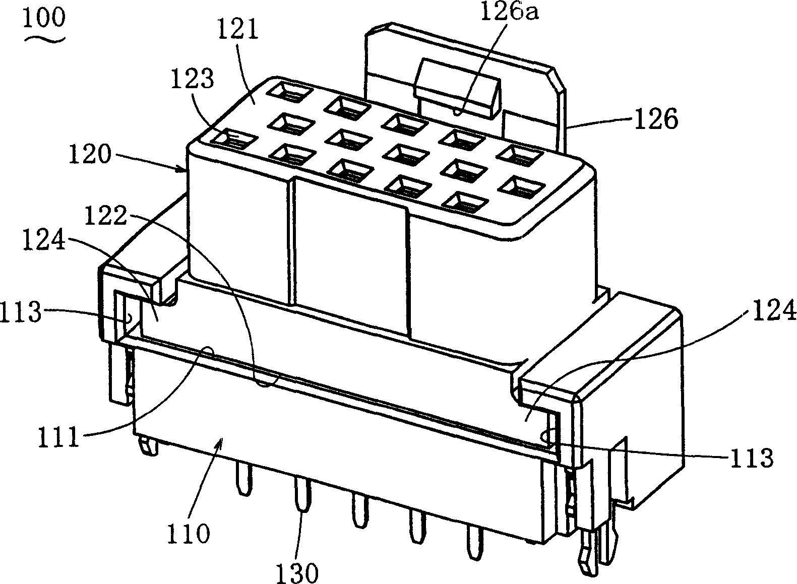
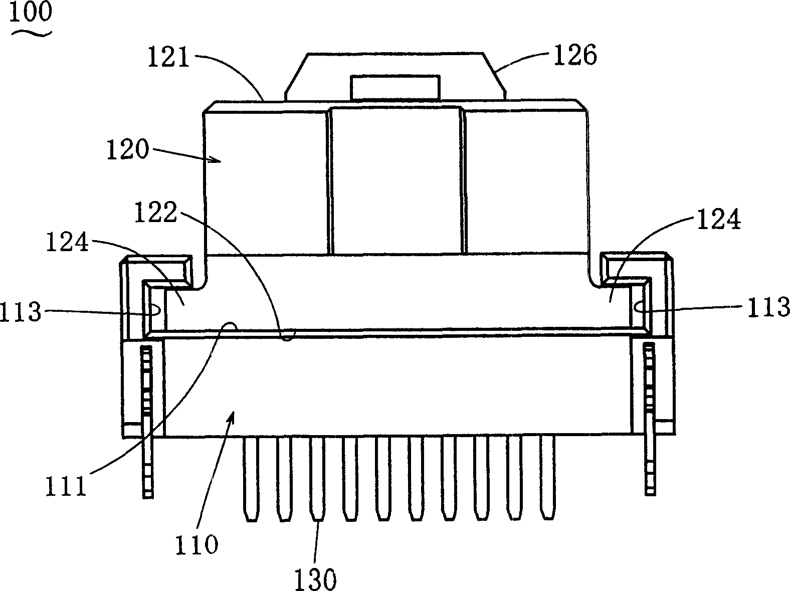
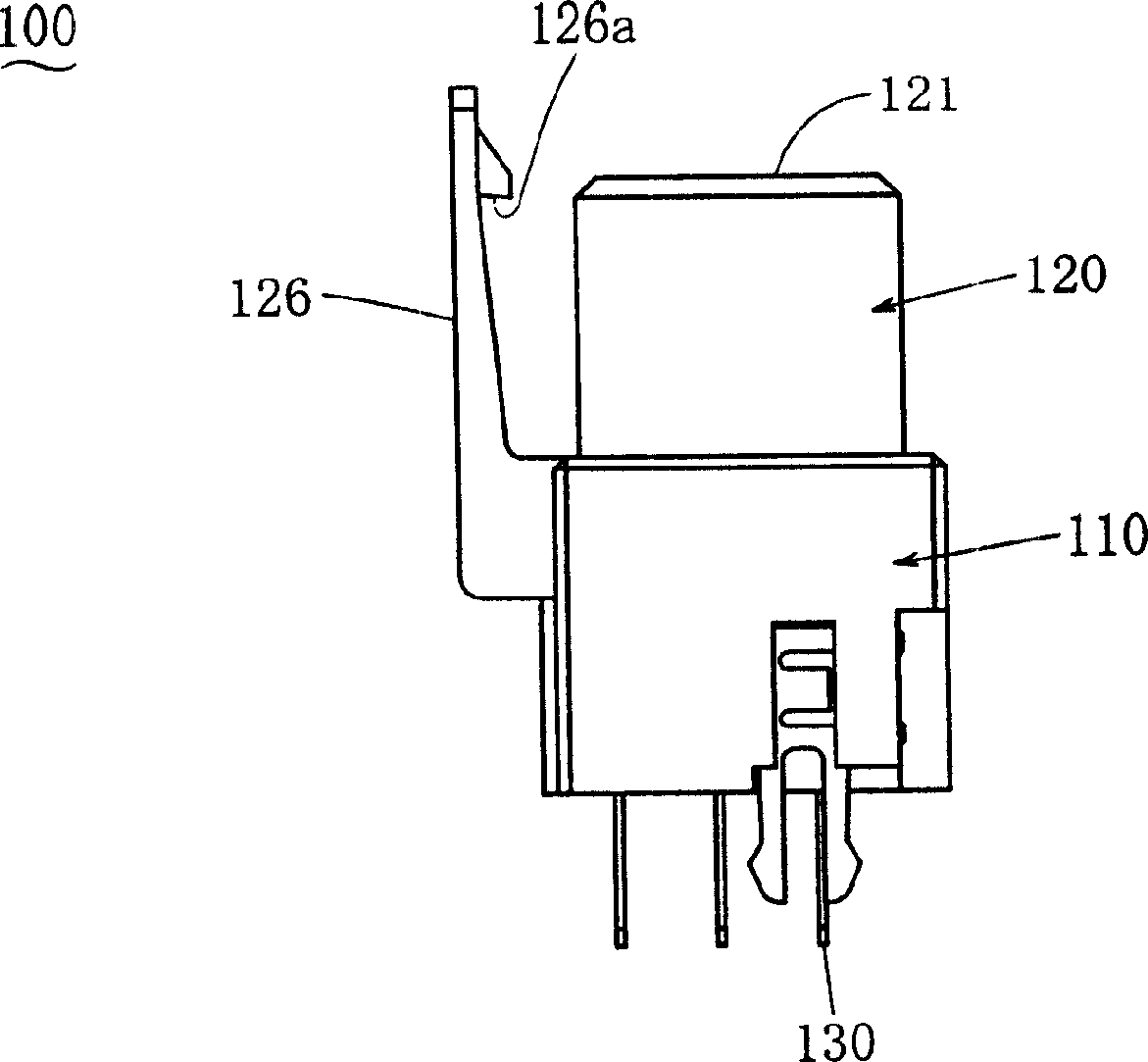
[0034] Embodiments of the present invention will be described below. Figure 1 to Figure 7 A floating connector 100 in an embodiment of the invention is shown. The floating connector 100 with Figure 11 and Figure 12 The opposite side connector 200 is shown mated or unplugged from the opposite side connector 200 . Fitting and extraction are performed along the height direction. The floating connector 100 of this embodiment has the convex portion 121 which is fitted by being fitted into the concave portion 211 of the opposite-side connector 200 , but this relationship is also possible in reverse. In addition, the floating connector 100 of this embodiment has a female contact (female contact) 130 by fitting with a male contact (male contact) 220 of the connector 200 on the opposite side. To achieve the connection, and this relationship is also possible in reverse. The description will be given using the mutually orthogonal depth direction,...


PUM


Abstract

To provide a floating connector wherein strengths against pull-out forces in the height direction are high and both housings are resistant to separation, the slide housing slides in any direction perpendicular to the height direction to reliably absorb the deviation in the position of the floating connector in relation to that of the counterpart connector without resulting in any defective contact with the counterpart contacts nor buckling of the contacts, the floating connector can be produced easily, and the floating connector has a high self-supportability through setting an appropriate rigidity of the contacts. It is a floating connector wherein the connecting parts of the contacts are pressed into the base housing, the contacting parts of the contacts are pressed into the slide housing, and both housings are so related to each other by means of protruding parts protruding in the width direction and grooves into which the protruding parts are inserted that both housings can slide in any directions perpendicular to the height direction.

Description

technical field [0001] The invention relates to a floating connector which belongs to the field of electrical connectors, and even if the relative position of the connector on the opposite side deviates, it can absorb the deviation and fit into the connector on the opposite side. Background technique [0002] JP 7-22865 has disclosed a multi-pole connector. The connecting terminal of this multi-pole connector has a contact portion at its uppermost end and a solder tail at its lowermost end, and is pressed into a plurality of connecting terminal fixing holes provided on the inside of the insulator housing for receiving and holding the connecting terminal. The base portion of the contact portion of the corresponding connection terminal is fixed, and the multistage connector has only one fixing mechanism for each connection terminal. In the case of such a multi-pole connector, in order to absorb and adjust the relative deviation in the two directions perpendicular to the conta...

Claims


Application Information

Patent Timeline
Patent Type & Authority Applications(China)
IPC IPC(8): H01R13/631
CPCH01R12/716H01R23/7073H01R13/6315
Inventor 盐田晃司东内优一松本光大
Owner JST MFG CO LTD
Learn More