Composite optical cable

A composite optical and optical cable technology, which is applied in the direction of insulated cables, power cables, cables, etc., can solve the problems of easy breakage of conductors and low impact strength, and achieve the effect of compact internal structure, high overall strength, and compact overall structure

Active Publication Date: 2016-01-06
SHANDONG QUANXING YINQIAO OPTICAL & ELECTRIC CABLE SCI & TECH DEV +1
View PDF7 Cites 7 Cited by
  • Summary
  • Abstract
  • Description
  • Claims
  • Application Information

AI Technical Summary

Problems solved by technology

[0003] However, the existing optical cables are usually set independently, so that the impact resistance is not high, and the conductor is easy to break after being twisted, so it is necessary to improve

Method used


Image

  • Composite optical cable
  • Composite optical cable

Examples


Embodiment Construction

[0018] The following are specific embodiments of the present invention and in conjunction with the accompanying drawings, the technical solutions of the present invention are further described, but the present invention is not limited to these embodiments.

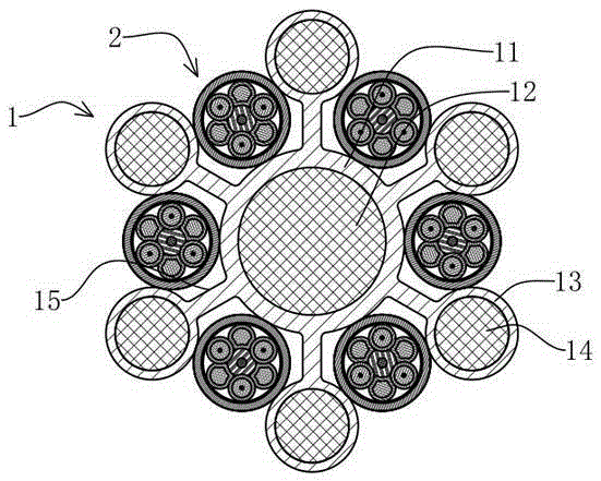
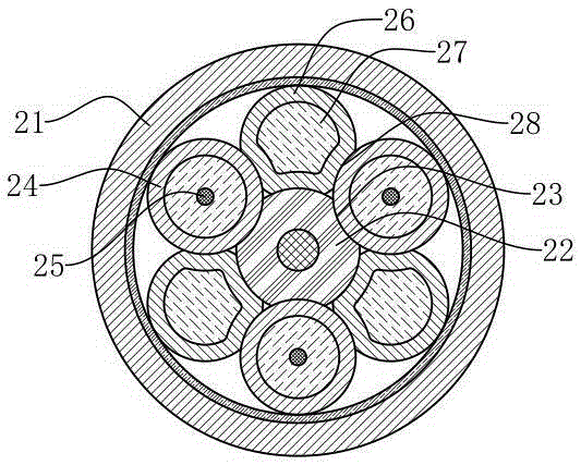
[0019] like figure 1 and figure 2 As shown, a composite optical cable of the present invention includes a support frame 1 and an optical cable 2. The support frame 1 includes a tubular central support tube 11 and several tubular edge support tubes 13. The outer wall of the central support tube 11 is connected with several strip-shaped thin Fins 15, one side of the long side of the fins 15 is connected to the outer wall of the central support tube 11, the other side of the long side of the fins 15 is connected to the outer wall of the edge support tube 13, and the center support tube 11 and the edge support tube 13 are respectively pierced with Central rib 12 and edge rib 14, an optical cable 2 is arranged between adjacen...


PUM


Abstract

The invention provides a composite optical cable and belongs to the field of optical cables. The composite optical cable solves the problem that an existing optical cable is low in strength. The composite optical cable comprises a supporting frame and optical cable wires. The supporting frame comprises a central supporting tubes and a plurality of edge supporting tubes which are connected through fins. The central supporting tube and the edge supporting tubes are respectively and internally provided with central reinforcing ribs and edge reinforcing ribs. One optical cable wire is arranged between two adjacent fins. The central supporting tube and two edge supporting tubes are abutted against the outer wall of one optical cable wire. Each optical cable wire comprises a sheath layer and a central reinforcing member. A plurality of sleeves I and sleeves II are arranged between the sheath layer and the central reinforcing member at intervals. The sleeve I is internally provided with a conductor. The sleeve II is internally filled with a buffering material. Outer walls of the sleeves II and the central reinforcing member are respectively provided with a plurality of strip-shaped grooves I and strip-shaped grooves II. Outer walls of the sleeves I and the central reinforcing member are respectively abutted in the strip-shaped grooves I, and the outer walls of the sleeves I are further abutted in the strip-shaped grooves II. The composite optical cable is higher in strength and better in distortion resistance.

Description

technical field [0001] The invention belongs to the technical field of optical cables and relates to a composite optical cable. Background technique [0002] Optical cable is an integrated transmission medium that organically combines metal wires and optical fibers to transmit electrical energy and optical information at the same time, on the same path, and in the same direction. It realizes the integration of power flow, business flow and information flow. [0003] However, the existing optical cables are usually installed independently, so that the impact resistance is not high, and at the same time, the conductor is easy to break after being twisted, so it is necessary to improve. Contents of the invention [0004] The purpose of the present invention is to provide a composite optical cable with compact structure, higher overall strength and better anti-twist performance to solve the above problems in the prior art. [0005] The purpose of the present invention ca...

Claims


Application Information

Patent Timeline
Patent Type & Authority Applications(China)
IPC IPC(8): H01B7/18H01B9/00
Inventor 韩玉权徐增
Owner SHANDONG QUANXING YINQIAO OPTICAL & ELECTRIC CABLE SCI & TECH DEV
Why Eureka
Try Eureka