Motor with two-end output

A technology of output shaft and motor body, which is applied in the direction of electrical components, electromechanical devices, electric components, etc.

Inactive Publication Date: 2005-02-23
许晓华
View PDF0 Cites 4 Cited by
  • Summary
  • Abstract
  • Description
  • Claims
  • Application Information

AI Technical Summary

Problems solved by technology

[0003] The present invention aims to solve the problem that the existing motors only have single-end output, and aims to pro

Method used


Image

  • Motor with two-end output
  • Motor with two-end output
  • Motor with two-end output

Examples


Embodiment Construction

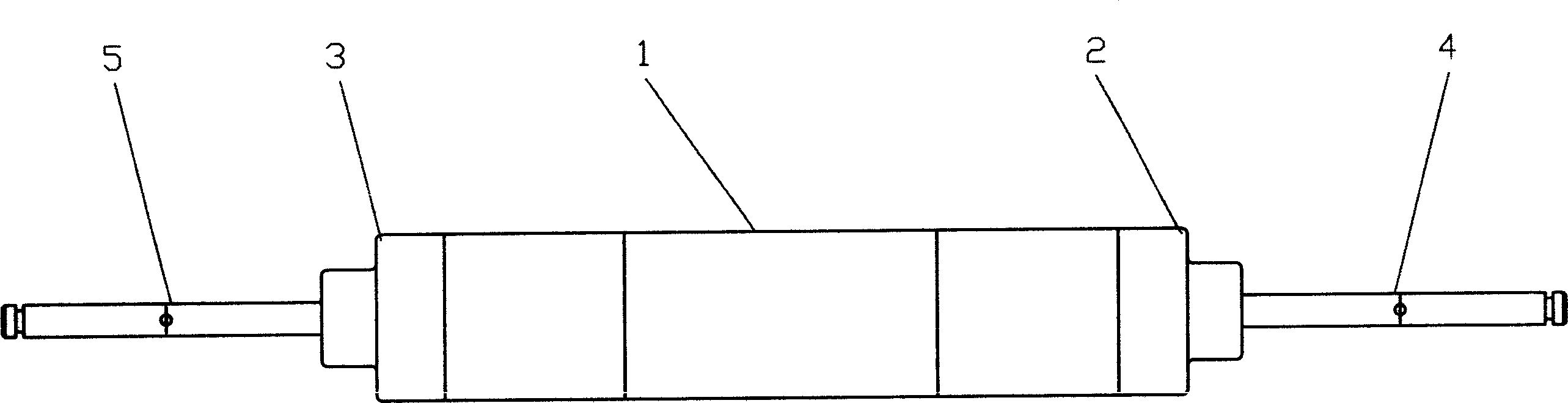
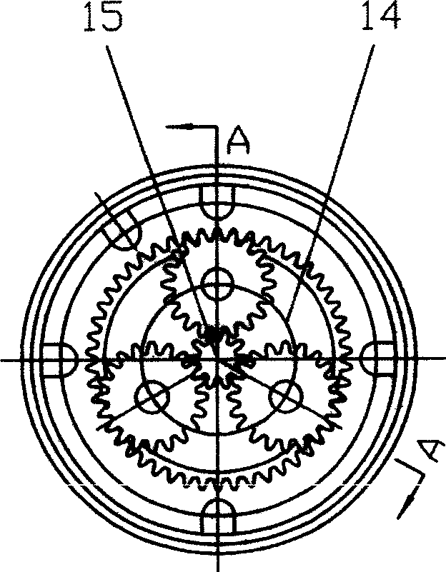
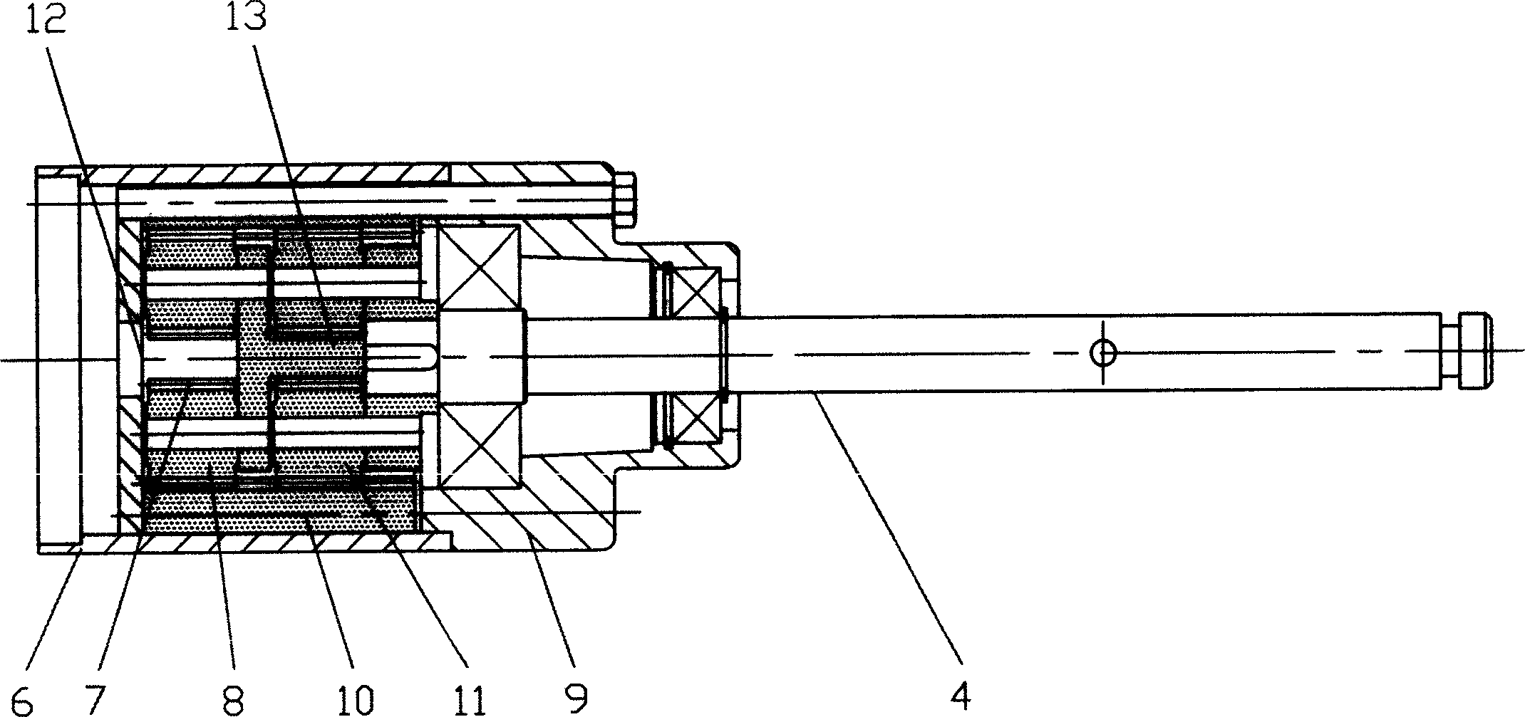
[0011] refer to figure 1 , The motor output at both ends, the motor body 1 adopts a standard permanent magnet DC motor with a power of 150W, and both ends of the motor body 1 are provided with a transmission shaft and gear reduction boxes 2 and 3. refer to figure 2 , 3 , the figure shows the structure of the gear box 2 at the right end. The gear reduction box 2 includes a box body 6, a box cover 9, a reduction gear set and an output shaft 4. The reduction gear set includes a first gear 7, a second gear 8, a third gear 10, and a fourth gear that mesh with each other in sequence. 11 and the output gear 13, the first gear 7 is sleeved on the transmission shaft 12 of the motor body, the output gear 13 is connected with the output shaft 12; the first gear 7 is connected with the second gear 8, the fourth gear 11 External meshing is used with the output gear 13 , and internal meshing is used between the second gear 8 and the third gear 10 and the third gear 10 and the fourth gea...


PUM


Abstract

In this motor, the transmitting shaft and the gear decelerator are installed on each side of the motor, the wheel can be installed on the output shaft of the gear decelerator directly, the gear decelerator is designed with optimization according to the needs. The decelerating gear applies the inner and outer gearing alternately, thus ensures the concentricity of the transmitting shaft with the output shaft. The compact structure improves the performance of the device.

Description

technical field [0001] The present invention relates to a motor, in particular to a miniature motor, in particular to a motor with output at both ends. Background technique [0002] Existing micro motors, especially motors with output power below 1KW, are widely used in many fields such as industrial production, household appliances, operation and transportation, such as driving motors for robots on production lines, motors for electric bicycles, and transportation. The drive motor of the bag truck of raw materials or finished products, etc. The above motors all use single-end output, that is, only one drive shaft outputs torque from one end of the motor, and the structure is relatively simple. SUMMARY OF THE INVENTION [0003] The present invention solves the problem that the existing motor has only single-end output, and aims to provide a motor with two-end output, so as to enrich the types of products and meet some application requirements in special fields. The techn...

Claims


Application Information

Patent Timeline
IPC IPC(8): H02K7/00H02K7/116
Inventor 张雷金宇航
Owner 许晓华
Why Eureka
Try Eureka