
Tunable light wave guide dispersion compensator controlled by two-section erverse electrode oriented coupler

A technology of directional coupler and dispersion compensator, which is applied in the coupling of optical waveguide, electromagnetic wave transmission system, electrical components, etc., can solve the problems of unfavorable application, increase the circumference of optical microring, etc., and achieve the effect of great flexibility

Inactive Publication Date: 2005-03-02
ZHEJIANG UNIV
View PDF0 Cites 3 Cited by
  • Summary
  • Abstract
  • Description
  • Claims
  • Application Information

AI Technical Summary

Problems solved by technology

Mai Desheng and others of Bell Labs in the United States have obtained the coupling control by using the 2×2 Mach-Zehnder interference structure, but due to the limitation on the mechanism, there are limitations in the realization of the coupling coefficient, and, due to the structural requirements, the perimeter of the entire optical microring has to be increased, which is not conducive to the application

Method used


Image

  • Tunable light wave guide dispersion compensator controlled by two-section erverse electrode oriented coupler
  • Tunable light wave guide dispersion compensator controlled by two-section erverse electrode oriented coupler

Examples


Embodiment Construction

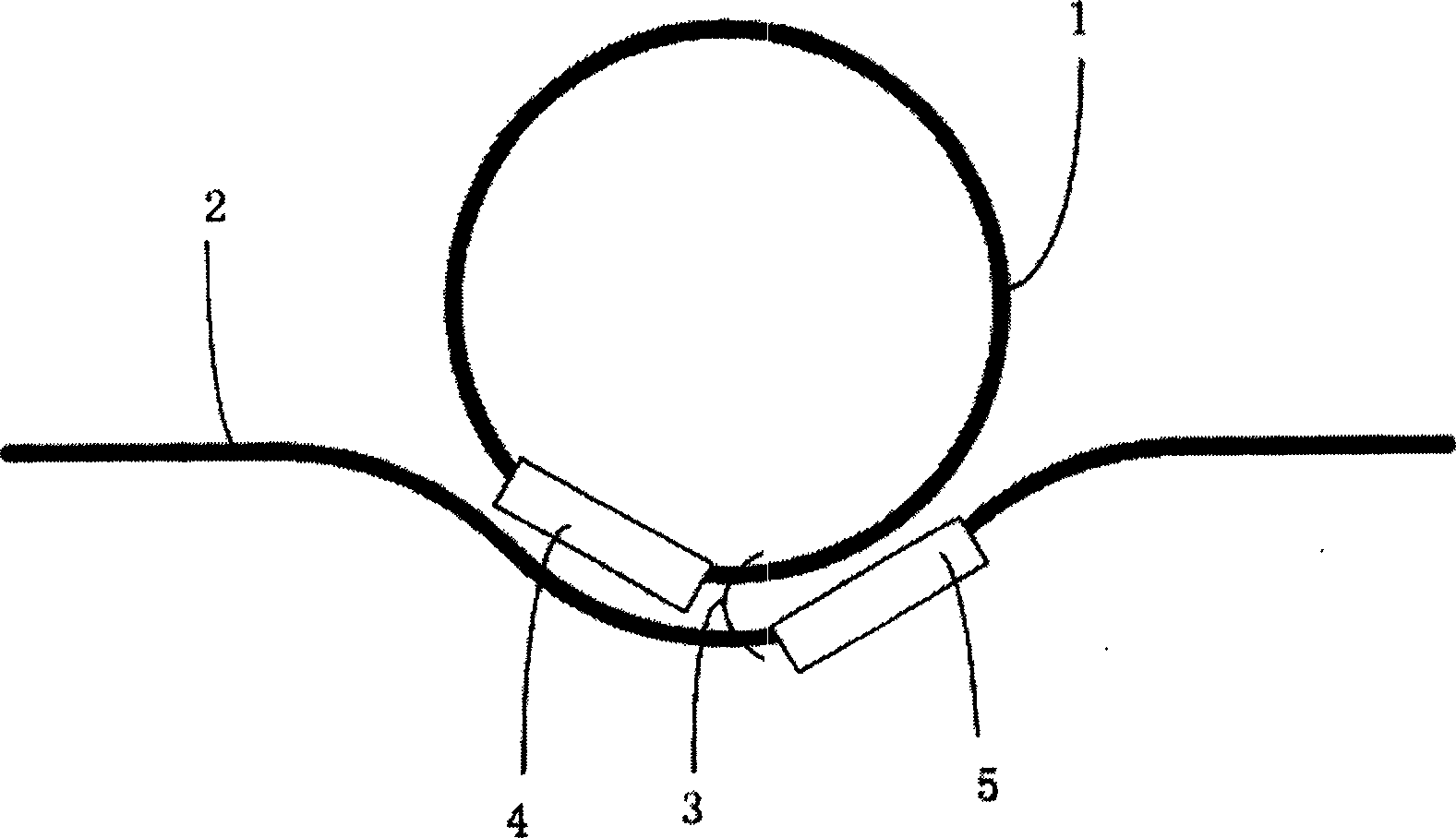
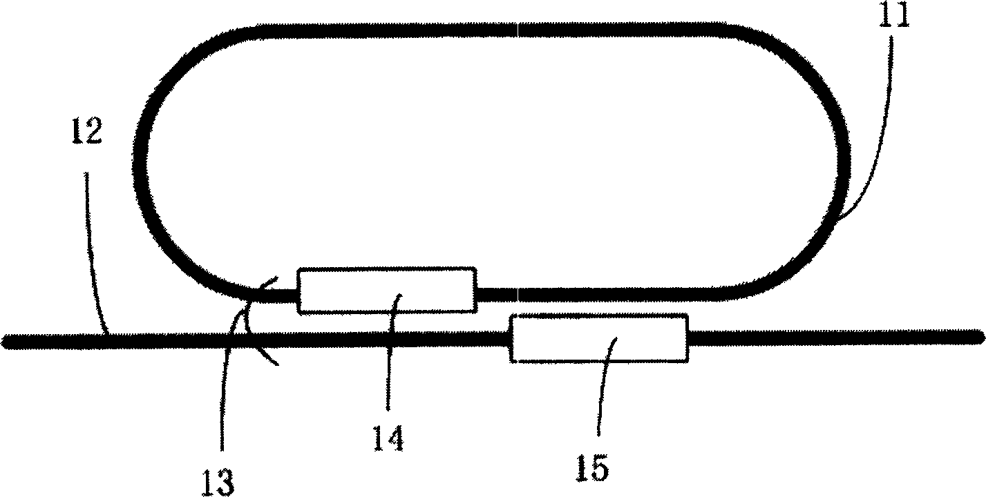
[0014] figure 1 and figure 2 It is an adjustable optical waveguide dispersion compensator controlled by a double-section reverse electrode directional coupler. figure 1 The optical waveguide microring 1 is circular, figure 2 The optical waveguide microring 11 is in the shape of a track and field track. Among them, 1 and 11 are optical waveguide microrings, 2 and 12 are input / output coupling optical waveguides, 3 and 13 are directional coupler parts with double-section inverted electrode structure, driving electrodes 4 and 14 and driving electrodes 5 and 15 The double-section reversed electrode parts are formed respectively. Of course, it should be explained here that the electrode structure is only schematic, and it will be specifically set according to the driving of the refractive index effect used.

[0015] There are many implementations of the present invention, and the silicon dioxide multilayer planar optical waveguide process is used as an example here, but it is ...


PUM


Abstract

The invention discloses a regulatable optical waveguide dispersion compensator controlled by binodal reverse-electrode orientation coupler, arranging parallel I / O optical waveguides in a part of the closed-loop optical waveguide microring to compose an orientation coupler, where the effective length of the orientation coupler is once to thrice as long as its coupled length and is a length influencing the coupling in the graded separation, two driving electrodes of the same length are arranged on the orientation coupler and reversely arranged on two waveguides composing the orientation coupler, thus composing the binodal reverse-electrode structural 2x2 input controllable orientation coupler. This structural regulable coupling mechanism can realize regulable coupling in the whole range and can have a bending shape, and even for a circular optical microring, it need not adopt special structure processing, thus unable to enlarge the circumference of the optical microring. This brings about extreme flexibility to the design and besides, it has extreme flexibility in designing and realizing multiple-stage cascade.

Description

technical field [0001] The invention relates to optical components, in particular to an adjustable optical waveguide dispersion compensator. Background technique [0002] With the increase of the communication rate in optical communication, the dispersion in the optical fiber has become the main factor limiting the optical transmission distance. Therefore, it has become extremely important to compensate the dispersion of the light wave transmitted in the optical fiber. At present, many optical dispersion compensation schemes have been proposed, among which the integrated optical waveguide optical dispersion compensator with optical microring structure based on the principle of all-pass filter is a very promising scheme. [0003] The optical waveguide dispersion compensator using the optical microring structure needs to have the input / output coupling control mechanism of the optical microring to realize the adjustable dispersion compensation function. Mai Desheng and others ...

Claims


Application Information

Patent Timeline
Patent Type & Authority Applications(China)
IPC IPC(8): G02B6/34H04B10/2525
Inventor 杨建义江晓清王帆李锡华周强王明华
Owner ZHEJIANG UNIV
Learn More