Liquid crystal display

A liquid crystal display, liquid crystal display panel technology, used in static indicators, instruments, nonlinear optics, etc.

Inactive Publication Date: 2005-03-02
AU OPTRONICS CORP
View PDF0 Cites 2 Cited by
  • Summary
  • Abstract
  • Description
  • Claims
  • Application Information

AI Technical Summary

Problems solved by technology

[0007] In view of this, the object of the present invention is to provide a liquid crystal display with improved driving capability of the g

Method used


Image

  • Liquid crystal display
  • Liquid crystal display
  • Liquid crystal display

Examples


Embodiment 1

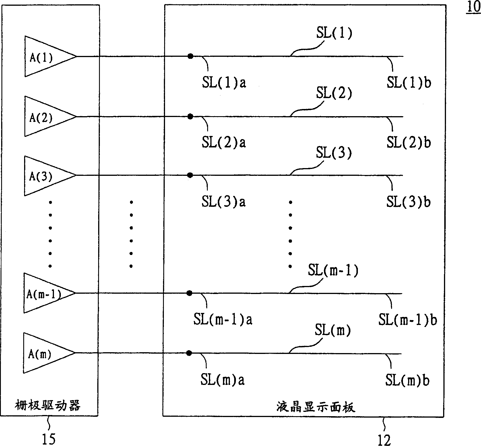
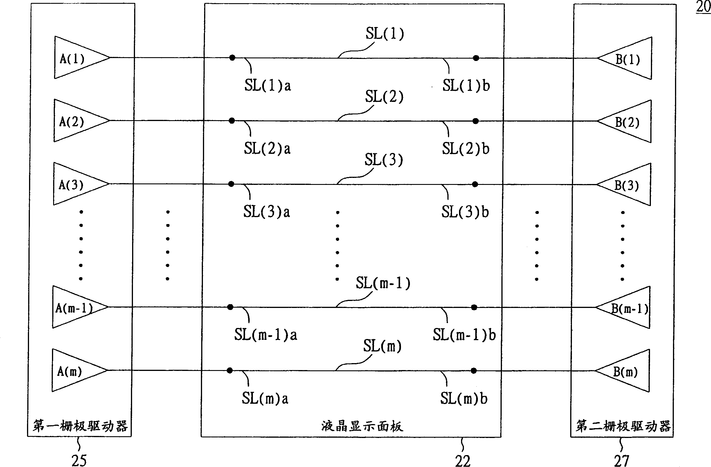
[0023] Please refer to figure 1 and figure 2 . Traditionally, m buffers are used to drive m scan lines in the way of driving scan lines on one side, that is, only one buffer is used to drive one scan line, such as figure 1 shown. Similarly, the traditional way of driving scan lines on both sides is also driven by a buffer at both ends of each scan line, such as figure 2 shown. Therefore, for a large-size liquid crystal display panel, the traditional driving method is likely to fail to drive the entire scanning line smoothly due to the insufficient driving capability of the buffer of the gate driver.

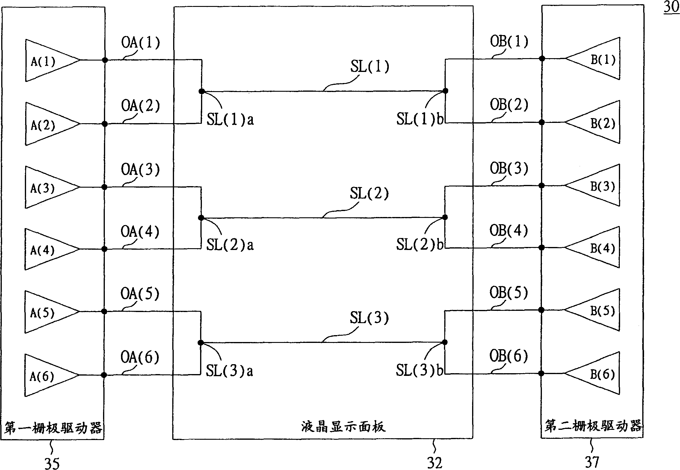
[0024] Please refer to image 3 , which represents a circuit diagram for driving the scan lines of the liquid crystal display panel according to the first embodiment of the present invention. The liquid crystal display 30 includes a liquid crystal display panel 32 and a first gate driver 35 . For example, the liquid crystal display panel 32 includes three scan lines, whi...

Embodiment 2

[0035] Please refer to Figure 5 , which represents a circuit diagram for driving the scan lines of the liquid crystal display panel according to the second embodiment of the present invention. The liquid crystal display 50 includes a liquid crystal display panel 52 , a first gate driver 55 and a second gate driver 57 .

[0036] The first gate driver 55 has 6 buffers, which are A( 1 )˜A( 6 ), and 3 output terminals, which are OA( 1 )˜OA( 3 ). The output terminals OA(1)-OA(3) are respectively electrically connected to the first terminals SL(1)a-SL(3)a of the scanning lines SL(1)-SL(3), and the output terminals OA(1)- OA( 3 ) is electrically connected to buffers A( 1 ) and A( 2 ), A( 3 ) and A( 4 ), and A( 5 ) and A( 6 ), respectively. Among them, the buffers A(1) and A(2), A(3) and A(4), and A(5) and A(6) have been electrically connected in the first gate driver 35, and then connected to the output The terminals OA(1)-OA(3) are electrically connected. That is to say, the bu...


PUM


Abstract

The invention is a liquid crystal display, including a liquid crystal display panel and a first grid driver, where the panel has M scanning lines, M being a positive integer and these scanning lines have first and second ends. The first grid driver is situated on one side of the panel to drive these scanning lines and has P buffers, where P is a positive integer greater than M, M of P buffers connect with first ends of M scanning lines, one-to-one, and the rest (P-M) buffers connect with the first end of any one of M scanning lines.

Description

technical field [0001] The present invention relates to a liquid crystal display (Liquid Crystal Display, LCD), and in particular to a liquid crystal display with improved driving capability of a gate driver. Background technique [0002] Due to the advantages of thin volume, light weight and low electromagnetic radiation, liquid crystal displays have gradually been favored by consumers in recent years. [0003] Please refer to figure 1 , which represents a conventional circuit diagram for driving scan lines of a liquid crystal display panel in a unilateral driving manner. The liquid crystal display 10 includes a liquid crystal display panel 12 and a gate driver 15 . The liquid crystal display panel 12 includes scan lines SL( 1 )˜SL(m). The gate driver 15 includes buffers A( 1 )˜A(m). The buffers A(1)-A(m) are electrically connected to the first ends SL(1)a-SL(m)a of the scanning lines SL(1)-SL(m) respectively, and are used to drive the scanning lines SL(1) )~SL(m). ...

Claims


Application Information

Patent Timeline
IPC IPC(8): G02F1/133G02F1/136G09G3/36
Inventor 施鸿民蔡宗光
Owner AU OPTRONICS CORP
Why Eureka
Try Eureka