
Cooling fin structure of magnetron

A technology for cooling fins and magnetrons, which is applied in the field of cooling fin structures, can solve the problems that the cooling fins cannot fluently heat, cannot effectively radiate heat, etc., and achieve the effect of effectively radiating heat

Inactive Publication Date: 2005-03-09
LG ELECTRONICS (TIANJIN) APPLIANCES CO LTD
View PDF0 Cites 1 Cited by
  • Summary
  • Abstract
  • Description
  • Claims
  • Application Information

AI Technical Summary

Problems solved by technology

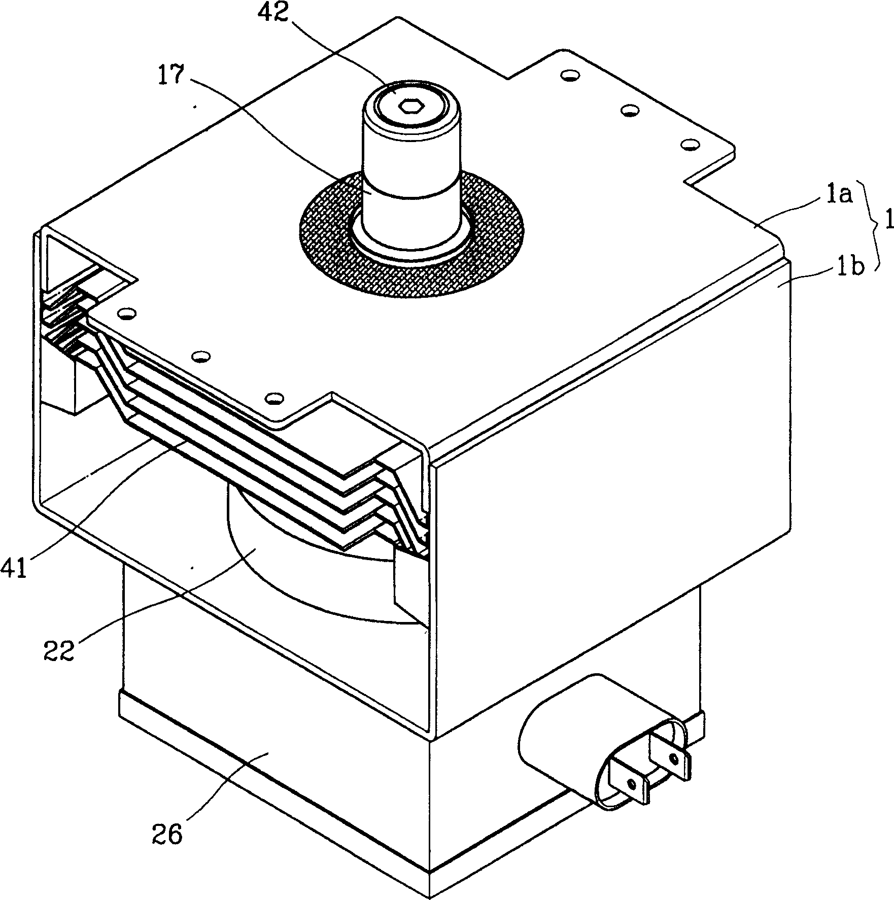
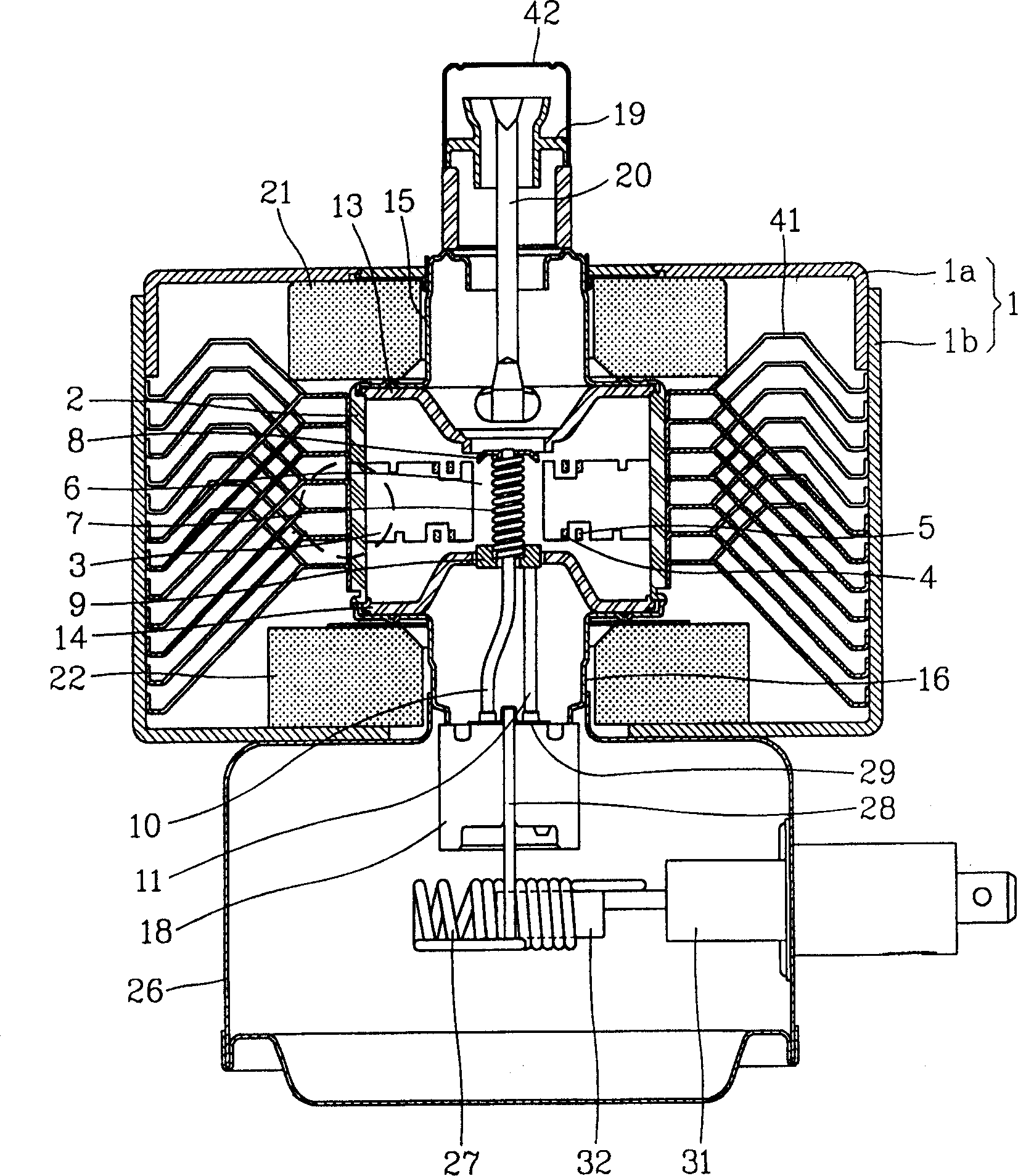
Therefore, when there is poor contact in the cooling fins (41), the above-mentioned cooling fins (41) cannot radiate heat smoothly, and thus cannot radiate heat effectively.

Method used


Image

  • Cooling fin structure of magnetron
  • Cooling fin structure of magnetron
  • Cooling fin structure of magnetron

Examples


Embodiment Construction

[0033] The present invention will be described in detail below with reference to the accompanying drawings and embodiments.

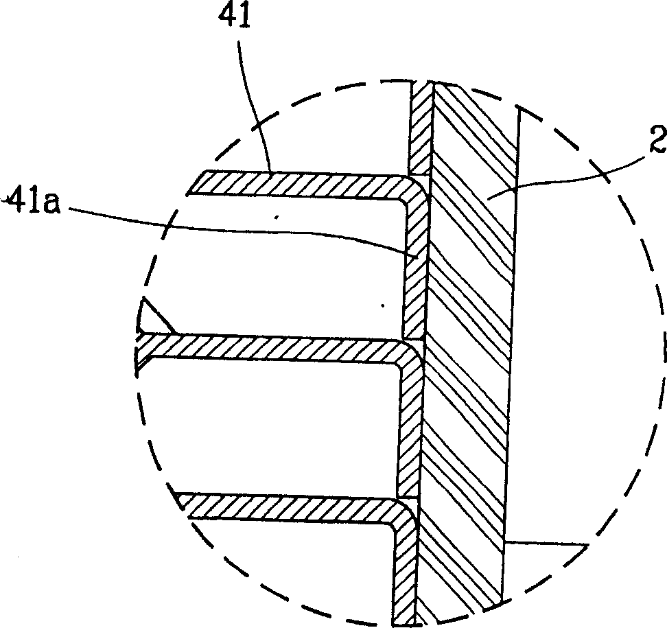
[0034] Figure 4 It is a longitudinal section structure diagram of the magnetron of the cooling fin structure of the present invention; Figure 5 It is a partial cross-sectional structure diagram of the cooling fin assembly state of the present invention.

[0035] As shown in the figure, the cooling fins (100) combined on the outside of the anode tank (2) of the present invention are formed by pressing into the body part (101) on the outer peripheral surface of the anode tank (2); The outer peripheral surface is integrally formed and constituted by a plurality of radiating fins (102) that transmit the heat transmitted by the body part (101) to the outside.

[0036] When the magnetron of the present invention constituted as above is in operation, the heat generated by the anode tank (2) is transferred to the body (101) of the cooling fin (100), and at ...


PUM


Abstract

The persent invention discloses a cooling fin structure of magnetron, belonging to collector cooling device of magnetron. In the magnetron whose cooling fin for radiating heat is pressed into outer side of another tank the heat-radiating vane can be integrally formed on the somatic portion of cooling fin mounted on the outer side of anode tank, so that the heat quantity produced on anode tank can be transferred through somatic portion of cooling fin, and the heat quantity transferred into the somatic portion can be simultaneously radiated by means of all the heat-radiating vanes, threrefore it can avoid imperfect contact in cooling fin, and can effectively release heat.

Description

technical field [0001] The present invention relates to a collector cooling device for a magnetron, and more specifically relates to a cooling fin structure for a magnetron in which cooling fins are integrally formed to increase heat release efficiency. Background technique [0002] As we all know, a magnetron is a device installed on a microwave oven or lighting equipment to convert electrical energy into high-frequency energy such as microwaves. [0003] The magnetron diagram of the existing structure is in figure 1 with figure 2 Above, as follows, the conventional magnetron structure will be briefly described. [0004] As shown in the figure, the upper yoke (1a) and the lower yoke (1b) form a "□"-shaped yoke (1) with a cylindrical anode tank (2) made of copper tubes, etc., and the anode tank ( 2) A plurality of blades (3) forming a resonator for inducing high-frequency components are arranged equidistantly in the inner direction of the axis, and the upper and lower pa...

Claims


Application Information

Patent Timeline
Patent Type & Authority Applications(China)
IPC IPC(8): H01J23/00
Inventor 文贤禄
Owner LG ELECTRONICS (TIANJIN) APPLIANCES CO LTD
Learn More