

Electric liquid processing device
A plasma treatment, plasma technology, used in circuits, discharge tubes, electrical components, etc.
- Summary
- Abstract
- Description
- Claims
- Application Information
AI Technical Summary
Problems solved by technology
Method used
Image

Examples
Embodiment 1
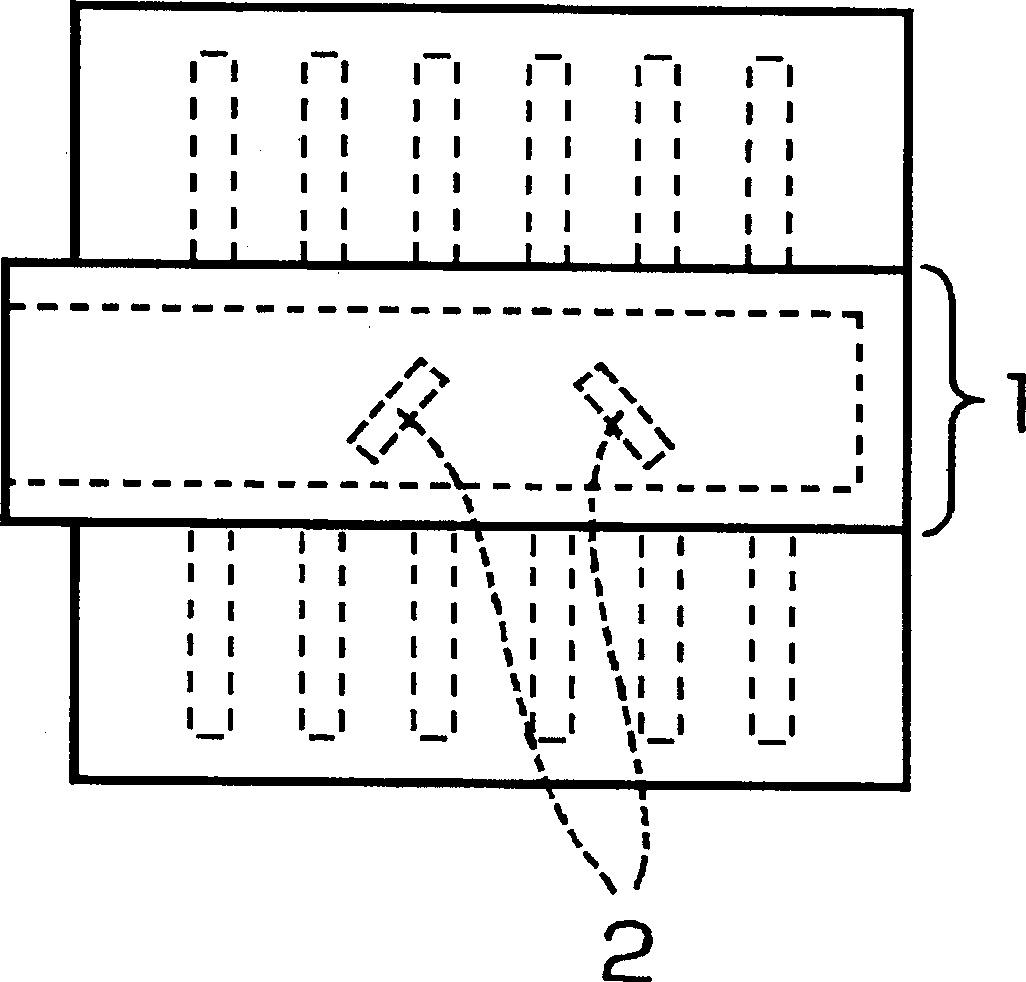
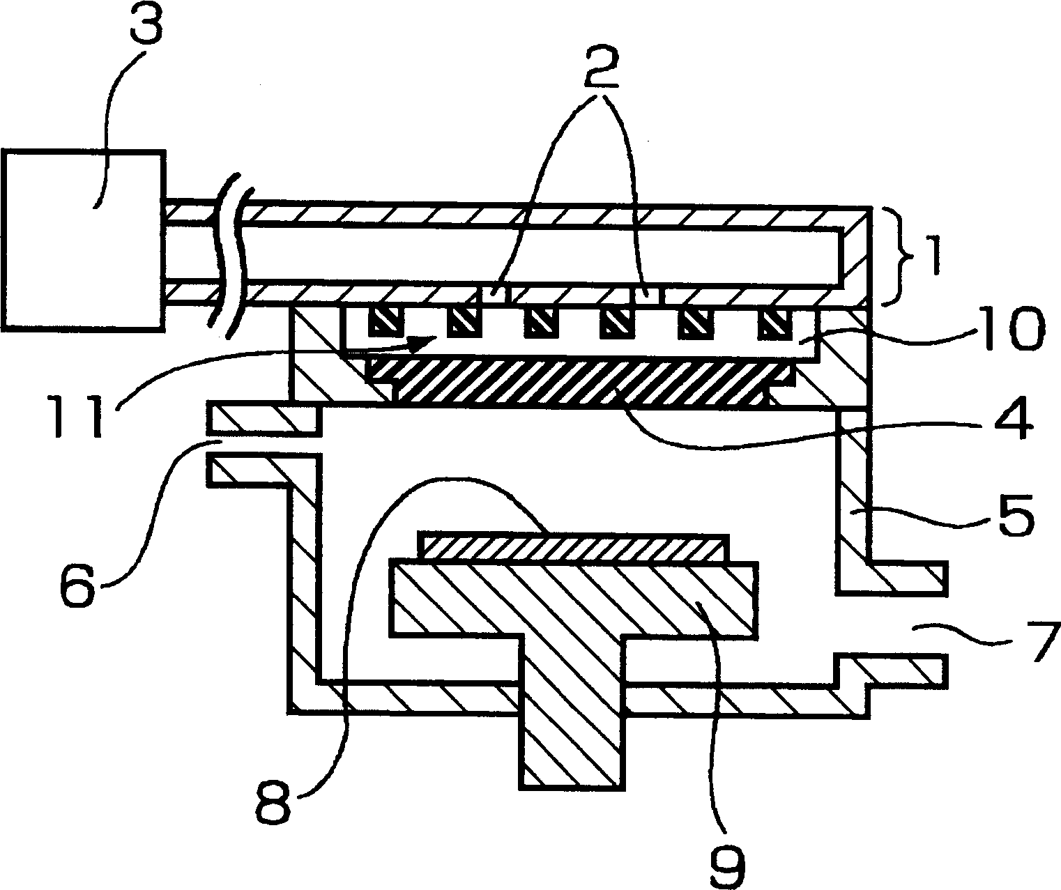
[0063] Fig. 1(a) is a plan view of the plasma processing apparatus of the first embodiment, and Fig. 1(b) is a cross-sectional view thereof.
[0064] Reference numeral 1 is a rectangular waveguide, 2 is a waveguide antenna, 3 is an electromagnetic wave such as a microwave source, 4 is an electromagnetic wave radiation window (electromagnetic wave introduction window) composed of a dielectric such as quartz, glass, and ceramics, and 5 is a Vacuum container, 6 is a gas introduction system, 7 is a gas discharge system, 8 is a substrate subjected to plasma treatment, 9 is a substrate mounting part, 10 is a dielectric sandwiched between the waveguide antenna 2 and the electromagnetic wave radiation window 4 The bulk space (for example, air) 11 is a concave-convex portion (concave-convex surface) provided on the surface of the waveguide 1 facing the electromagnetic wave radiation window 4 .
[0065] A gas introduction system 6 for introducing a source gas and a gas discharge system ...
Embodiment 2
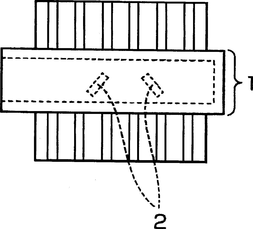
[0075] Fig. 2(a) is a plan view of the plasma processing apparatus of the second embodiment, and Fig. 2(b) is a cross-sectional view thereof.
[0076] Reference numeral 12 denotes a concavo-convex portion provided on the surface of the electromagnetic wave radiation window 4 facing the waveguide 1 .
[0077] In the second embodiment, on the surface of the electromagnetic wave radiation window 4 facing the waveguide 1 , elongated convex portions with a width of 10 mm and a depth of 5 mm are provided at intervals of 30 mm, thereby forming the concave-convex portion 12 .
[0078] The convex portion of the concave-convex portion 12 of the electromagnetic wave radiation window 4 is provided at a distance of 5 mm from the outer surface of the waveguide 1 on which the waveguide antenna 2 is provided. Furthermore, the surface of the electromagnetic wave radiation window 4 in contact with the plasma on the side opposite to the surface provided with the concave-convex portion 12 (that i...
Embodiment 3
[0084] Fig. 3(a) is a plan view of the electromagnetic wave radiation window in the plasma processing apparatus of the third embodiment, and Fig. 3(b) is a cross-sectional view thereof.
[0085] Reference numeral 13 is a glass plate constituting the electromagnetic wave radiation window 4 , and 14 is a mixing member made of spherical ceramics mixed with the glass plate 13 .
[0086] In Example 3, a glass plate (dielectric constant 4.7) 13 mixed with a mixing member 14 made of ceramics such as alumina (dielectric constant 9) is used as the electromagnetic wave radiation window 4 .
[0087] In addition, the diameter of the mixing member 14 made of spherical ceramics is 2.5 cm, and the thickness of the electromagnetic wave radiation window 4 is 5 cm. The diameter of the spherical mixing member 14 is larger than 1 / 8 of the wavelength of the microwave. Therefore, microwaves can be effectively dispersed due to reflection or scattering. As mentioned above, by using the electromagne...
PUM
 Abstract
Description
Claims
Application Information