End set multi roller grinder

A mill and roller technology, which is applied in the field of material grinding equipment, can solve the problems of grinding drum beating or vibration and noise, low production efficiency, high manufacturing cost, etc., and achieve reduced noise, stable operation, reduced friction and wear and power The effect of consumption

Inactive Publication Date: 2005-03-23
郝志刚
View PDF1 Cites 5 Cited by
  • Summary
  • Abstract
  • Description
  • Claims
  • Application Information

AI Technical Summary

Problems solved by technology

The disadvantages of this barrel roller mill are that the production efficiency is low because a single set of grinding rollers and the grinding cylinder only constitute a complete axial running-in surface; while multiple sets of grinding rollers have complex structures, which are difficult to achieve in actual production. implementation, and the manufacturing cost is high; in addition, its supporting member only acts as a support constraint to the vertical downward direction of the grinding cylinder, while the other directions along the circumference are in an unconstrained free state. Therefore, during operation, the grinding cylinder is easy to Jumping or vibration and noise are generated, especially when there are multiple rollers running in the grinding cylinder, it is easy to generate unbalanced force, which will aggravate these phenomena

Method used


Image

  • End set multi roller grinder
  • End set multi roller grinder
  • End set multi roller grinder

Examples


Embodiment 1

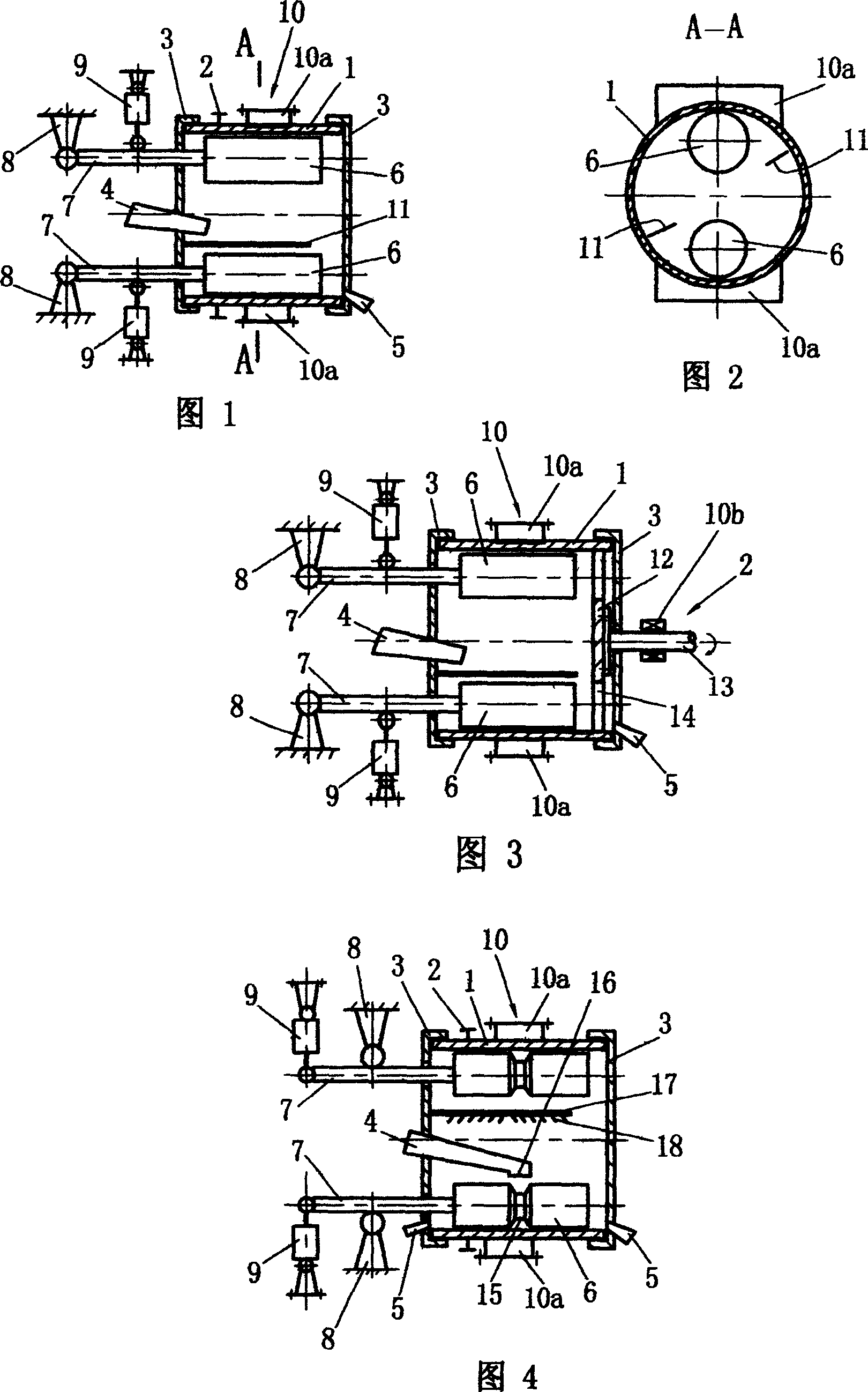
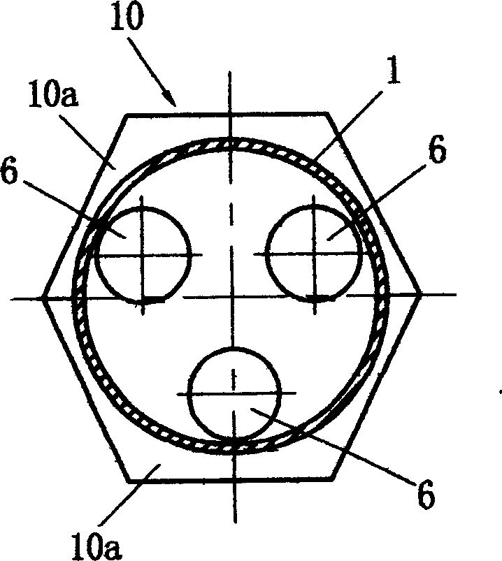
[0018] Embodiment 1, see Fig. 1, Fig. 2.

[0019] There are a grinding cylinder 1 and a grinding cylinder driving mechanism 2. There are end caps 3 at both ends of the grinding cylinder, and a feeding device 4 and a discharge port 5 are provided on the end side of the grinding cylinder. Inside the grinding cylinder 1 are grinding mills distributed along the circumferential direction of the grinding cylinder. Roller 6, when the driving mechanism is working, the grinding cylinder can rotate relative to the end cover; the driving mechanism 2 in this example is a gear-type driving mechanism, and there are two grinding rollers 6 inside the grinding cylinder 1, which are shown along the circumferential direction of the grinding cylinder Evenly distributed, that is, symmetrical up and down, each grinding roller and the inner wall of the grinding cylinder form a complete grinding surface, one end of each grinding roller 6 is connected to a roller shaft 7, and the outer section of each ...

Embodiment 2

[0020] Embodiment 2, see Fig. 3.

[0021] The driving mechanism of this example adopts another kind of structure to realize. As shown in Figure 3, the driving mechanism 2 is a transmission shaft type structure, including a component 12 that is located in the grinding cylinder 1 and connected to the end of the grinding cylinder, and a transmission shaft 13 connected with the component. The shaft 13 protrudes from the end cover 3 of this side; the transmission shaft 13 is provided with a supporting device 10b constraining the circumferential direction of the grinding cylinder, that is, the supporting system 10 of this example consists of a support system 10b located on the outer wall of the grinding cylinder 1, which is placed on the circumference of the grinding cylinder. The support device 10a of direction support constraint and the support device 10b that is located on the transmission shaft 13 constitute;

Embodiment 3

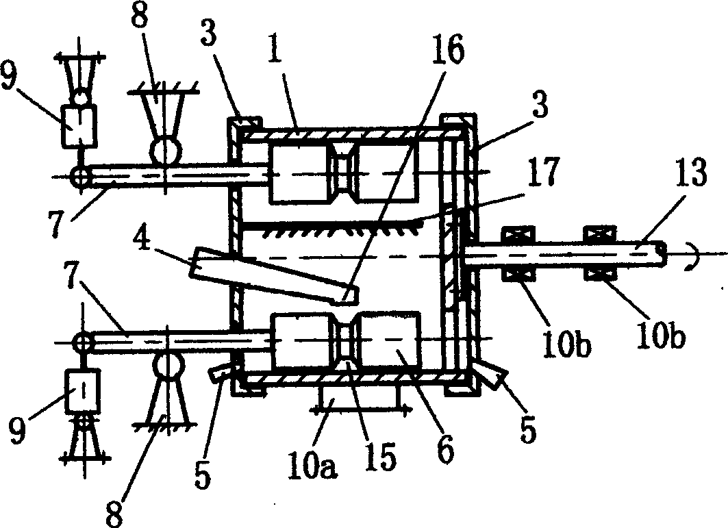
[0022] Embodiment 3, see Fig. 4.

[0023] In this example, the pressurizing mechanism 9 is set on the roller shaft section outside the hinge support 8; the middle part of the grinding roller 6 is provided with a groove 15, and the feeding port 16 of the feeding device 4 is located at the The middle part of the roller 6 corresponds to the groove 15; in addition, a two-way feeder 17 is provided in the grinding cylinder to allow the material to flow from the middle of the grinding roller 6 to both ends, and it is connected to the end cover, and the two-way feeder 17 is set The component 18 that makes the material flow from the middle of the grinding roller to both ends, during the implementation process, the scraper in the grinding cylinder can be combined with the bidirectional feeding device 17, or can be set separately from the bidirectional feeding device 17; The end caps at both ends of the barrel are provided with a discharge port 5, and the others are the same as in Embodi...


PUM


Abstract

A multi-roller grinder is composed of grinding cavity with a central feeder and two discharge ports at both ends, at least two grinding rollers with central ring slot relative to said feeder, grinding roller driving mechanism, bidirectional material guiding unit, and pressurizing unit of said grinding rollers.

Description

technical field [0001] The invention relates to material grinding equipment, in particular to an end-mounted multi-roller roller mill. Background technique [0002] The "90100329.8" patent application specification published on August 7, 1991 discloses a barrel roller mill, which is a "end-mounted roller structure", that is, the roller only passes through the roller at one end. axis for positioning. The roller mill has a grinding cylinder and a driving mechanism for the grinding cylinder. There are grinding rollers in the grinding cylinder, end covers at both ends of the grinding cylinder, feeding devices and discharge ports on the end side of the grinding cylinder, and one end of the grinding roller is connected A roller shaft, the outer section of the roller shaft protrudes from the end cover, and is connected with the support, and the roller shaft section inside or outside the support is provided with a pressurizing mechanism acting on the grinding roller. The cylinder ...

Claims


Application Information

Patent Timeline
Patent Type & Authority Applications(China)
IPC IPC(8): B02C15/04
Inventor 郝志刚
Owner 郝志刚
Why Eureka
Try Eureka