Projection type video display

An image display device and projection technology, which can be applied in the direction of using a projection device, image reproducer, projection device, image communication, etc., can solve the problems of blocking air flow and reducing cooling capacity, etc.

Inactive Publication Date: 2005-03-30
SANYO ELECTRIC CO LTD
View PDF1 Cites 4 Cited by
  • Summary
  • Abstract
  • Description
  • Claims
  • Application Information

AI Technical Summary

Problems solved by technology

However, if such a shading plate 25 is provided, the size of the device will be increased, and the flow of air will be blocked, thereby reducing the cooling capacity.
Furthermore, even if the shading plate 25 is provided on the downstream side of the ozone decomposition catalyst filter 23, the same problem will occur.

Method used


Image

  • Projection type video display
  • Projection type video display
  • Projection type video display

Examples


Embodiment Construction

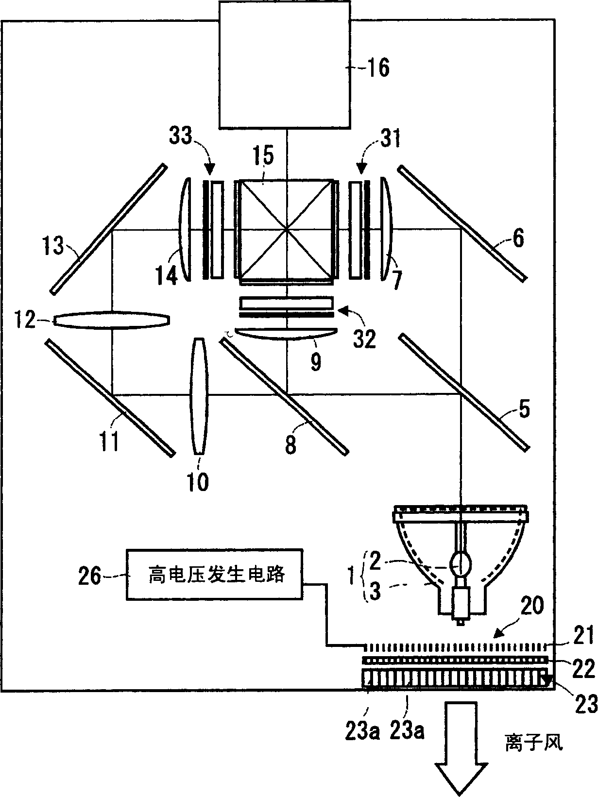
[0018] Below, according to Figure 1 to Figure 3 , the projection type image display device according to the embodiment of the present invention will be described.

[0019] figure 1 It is a diagram showing the optical system of the 3-panel color liquid crystal projector. The light emitting unit 2 of the light source 1 is composed of an ultra-high pressure mercury lamp, a metal halide lamp, a xenon lamp, etc., and the irradiated light is converted into parallel light by, for example, a parabolic reflector 3 and emitted.

[0020] The first dichroic mirror 5 transmits light in the red wavelength band and reflects light in the cyan (green+blue) wavelength band. The light in the red wavelength band passing through the first dichroic mirror 5 is reflected by the total reflection mirror 6 to change the optical path. The red light reflected by the total reflection mirror 6 passes through the condensing lens 7 and passes through the transmissive liquid crystal light valve 31 for re...


PUM


Abstract

An ion wind generator is provided behind a light source. The ion wind generator 20 negatively-ionizes air by corona discharges using needle-shaped electrodes on the negative side, and draws the negatively-ionized air by a mesh electrode on the ground side to generate an air current. An exhaust port is provided with an ozone decomposition catalyst filter. A path axis for vent holes in the ozone decomposition catalyst filter is inclined to the direction of advancement (a direction toward the exhaust port) of unnecessary light from a lamp from the light source, and the unnecessary light from a lamp is shaded by the ozone decomposition catalyst filter.

Description

technical field [0001] The present invention relates to projection type image display devices such as liquid crystal projectors. Background technique [0002] Projection-type image display devices are configured to project the light emitted from the light source after being modulated by a light valve such as a liquid crystal panel. Therefore, a high-brightness light source is required, and the heat generated by the high-brightness light source itself or the polarization of the light by the liquid crystal panel are required. As a countermeasure against the heat generated when absorbing chips or various optical parts, conventionally, a motor is used to rotate a fan to suck or exhaust air to discharge the heat to the outside of the device (see Patent Document 1). [0003] 【Patent Document 1】 [0004] Japanese Patent Application Publication No. 2001-222065 [0005] However, in the suction and exhaust mechanism driven by the motor, the noise of the suction and exhaust sound is ...

Claims


Application Information

Patent Timeline
Patent Type & Authority Applications(China)
IPC IPC(8): G03B21/16G02F1/13G03B21/00G03B21/14H01T23/00H04N5/66H04N5/74H04N9/31
CPCH04N9/3144H04N9/3197H04N9/3141H01T23/00
Inventor 池田贵司石井孝治
Owner SANYO ELECTRIC CO LTD
Why Eureka
Try Eureka