Optical display device with switchable visual angle

An optical display and viewing angle technology, applied in optics, identification devices, nonlinear optics, etc., can solve problems such as troublesome use, inability to observe the content displayed on the screen, and darkening of the screen

Active Publication Date: 2005-04-06
AU OPTRONICS CORP
View PDF4 Cites 2 Cited by
  • Summary
  • Abstract
  • Description
  • Claims
  • Application Information

AI Technical Summary

Problems solved by technology

[0003] 1. In Toshiba's U.S. patent announcement No. US6445434B2, an alignment layer (Alignment layer) technology is disclosed, which uses the difference in the rubbing direction (rubbing direction) of interconnected pixels on the alignment layer to enable the observer to observe at a large viewing angle. The image is greatly blurred due to grayscale inversion, and the display content of the screen cannot be observed from a specific viewing angle in front of the screen
But the disadvantage of the above technique is that this layer must be removed when the narrow viewing angle is not needed
[0004] 2. In Rockwell's U.S. Patent No. US6239853B1, a structure is disclosed to cause light to have a specific

Method used


Image

  • Optical display device with switchable visual angle
  • Optical display device with switchable visual angle
  • Optical display device with switchable visual angle

Examples


no. 1 example

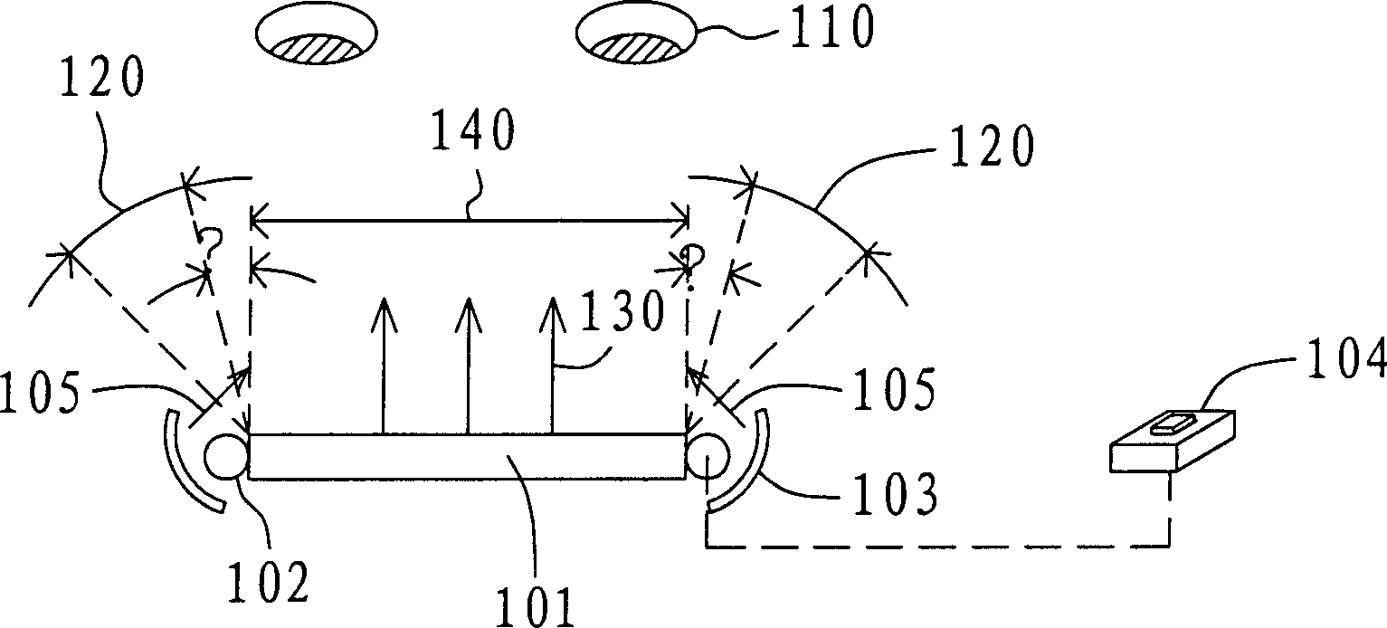
[0017] Please refer to figure 1 , which is a schematic diagram of the optical display device with switchable viewing angle according to the first embodiment. The optical display device 100 with switchable viewing angle includes: a display panel 101 , a light interference component 102 , a light guiding component 103 and a switch 104 . The display panel 101 is used for displaying images, and the viewer 110 is directly in front of the display panel 101 . In the first embodiment, the light guide component 103 is a reflector, and the display panel 101 can be a liquid crystal screen, a plasma screen, or an organic light-emitting display screen. The light interference component 102 can be a cold cathode fluorescent lamp (cold cathode fluorescent lamp; CCFL) or a light emitting diode (light emitting diode; LED) as a light source for providing the interference light 105 . The light interference component 102 can be disposed on one side or each side of the display panel 101 , and the...

no. 2 example

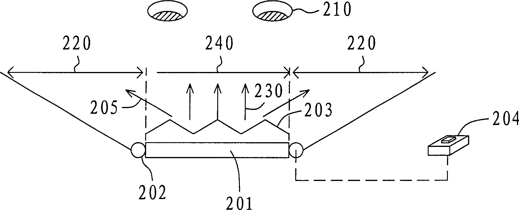
[0019] Please refer to figure 2 , which is a schematic diagram of an optical display device with a switchable viewing angle according to the second embodiment. The optical display device 200 with switchable viewing angle includes: a display panel 201 , a light interference component 202 , a light guiding component 203 and a switch 204 . The display panel 201 is used for displaying images, and a viewer 210 is directly in front of the display panel 201 . In the second embodiment, the light guide component 203 is a light guide plate. When the switch 204 activates the light interference component 202, the light interference component 202 emits the interference light 205, and the distribution of the interference light 205 on the display panel 201 is controlled by using the light guide component 203-light guide plate arranged in front of the display panel 201 in advance. The light guide assembly 203-light guide plate of the example controls the divergence of the interfering light...


PUM


Abstract

It is an optics display apparatus with switching perspective and its method, which comprises a display panel, one light interference elements, one light conductive element and a switch. The display panel is to display an image; the light interference element is aligned on one side of the display panel to provide interference light; the light conductive element is adjacent to the display panel to control the interference light direction and generate an image interference area in the visible area; the switch is to switch the interference light.

Description

technical field [0001] The present invention relates to an optical display device with a switchable viewing angle, and in particular to an optical display device using a light interference component in a flat-panel display to affect the viewing angle of the optical display device. Background technique [0002] Users of flat-panel displays wish to view the screen of the display only in a specific area or viewing angle, not in this specific area or viewing angle. people will not be able to see what is displayed on the monitor. In this regard, many related technologies are currently under development. For example, the following methods use specific technical features to achieve the display content of the display in a specific area or viewing angle: [0003] 1. In Toshiba's U.S. patent announcement No. US6445434B2, an alignment layer (Alignment layer) technology is disclosed, which uses the difference in the rubbing direction (rubbing direction) of interconnected pixels on the ...

Claims


Application Information

Patent Timeline
IPC IPC(8): G02F1/133G02F1/1335G09F9/00
Inventor 林永伦蔡孟璋苏振嘉陈伯纶
Owner AU OPTRONICS CORP
Why Eureka
Try Eureka