
Tread pattern structure capable of reducing rotative force

A pattern structure and tire surface technology, applied in tire tread/tread pattern, tire parts, transportation and packaging, etc., can solve the problems of large vehicle inclination and side roll

Inactive Publication Date: 2005-04-13
HANKOOK TIRE WORLDWIDE
View PDF0 Cites 0 Cited by
  • Summary
  • Abstract
  • Description
  • Claims
  • Application Information

AI Technical Summary

Problems solved by technology

As mentioned above, conventional tires having such a tread 101 have a large turning force when the vehicle turns, so the vehicle inclines greatly, and in severe cases, side roll occurs.

Method used


Image

  • Tread pattern structure capable of reducing rotative force
  • Tread pattern structure capable of reducing rotative force
  • Tread pattern structure capable of reducing rotative force

Examples


Embodiment Construction

[0013] The present invention will be described in detail below in conjunction with example drawings.

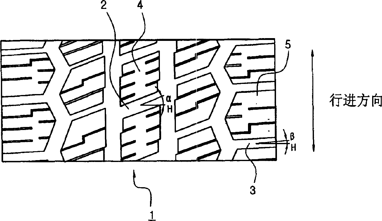
[0014] Fig. 1 is a partial plan view showing the tread structure of the tire tread of the present invention.

[0015] In the tread pattern structure for reducing the turning force of the present invention, the pattern has zigzag transverse grooves. The lateral grooves 2 in the central portion of the tread 1 and the lateral grooves 3 in the shoulder portion are inclined at a predetermined angle with respect to the horizontal transverse line H as a reference. Wherein, the angle α of the transverse groove 2 in the central portion 4 of the tire tread 1 is not less than 7° and not more than 15° based on the horizontal horizontal line H, and the angle β of the transverse groove 3 of the shoulder portion 5 is in the range of The horizontal horizontal line H is above 0° and below 5° of the reference.

[0016] Therefore, the actual contact area of ​​the tire tread 1 accounts for 62-...


PUM


Abstract

The present invention relates to a tire tread pattern structure which is related to the steering stability of a vehicle and reduces the turning force, and in particular relates to such a tire tread pattern structure which reduces the turning force. , which can prevent the large roll phenomenon when turning sharply while walking. In the tire tread pattern structure for reducing the rotational force of the present invention, the pattern has zigzag transverse grooves; the transverse grooves (2) of the central part (4) of the tire tread (1) and the transverse grooves of the shoulder part are The horizontal horizontal line H is inclined by a predetermined angle as a reference. Wherein, the angle α of the lateral groove (2) of the central part (4) of the tread (1) is 7° or more and 15° or less based on the horizontal transverse line H, and the angle α of the shoulder part (5) The angle β of the lateral groove (3) is 0° or more and 5° or less with respect to the horizontal horizontal line H as a reference.

Description

technical field [0001] The present invention relates to a tire tread structure that reduces cornering force related to the handling stability of a vehicle, and in particular relates to such a tire tread structure that reduces cornering force. At the same time of turning force, it prevents a large roll phenomenon when making a sharp turn while walking. Background technique [0002] Generally speaking, when the vehicle is running, the tires that move horizontally at a sideslip angle relative to the direction of travel and perform rotary motion will be subjected to lateral force in the direction of the tire axis due to the rotary resistance and the lateral deformation of the tire. In this lateral force , the turning force at right angles to the direction of travel plays an important role in turning the vehicle. [0003] In the past, various tires that can generate large turning forces have been developed to improve vehicle handling safety. Recently, with the development of le...

Claims


Application Information

Patent Timeline
Patent Type & Authority Applications(China)
IPC IPC(8): B60C11/03B60C11/13
CPCB60C11/03B60C11/033B60C2011/0372
Inventor 朴正铉
Owner HANKOOK TIRE WORLDWIDE
Learn More