Cooling water circuit system

A circuit system and cooling water technology, which is applied in the direction of engine cooling, coolant flow control, cooling device control device, etc., can solve the problem of poor warm-up performance of lubricating oil and other problems

Inactive Publication Date: 2005-04-13
DENSO CORP
View PDF1 Cites 19 Cited by
  • Summary
  • Abstract
  • Description
  • Claims
  • Application Information

AI Technical Summary

Problems solved by technology

On the contrary, when the cooling water after passing through the water tank is used in the heat exchanger to sufficiently cool the lubricating oil, the warm-up performance of the lubricating oil after the engine starts may be deteriorated

Method used


Image

  • Cooling water circuit system
  • Cooling water circuit system
  • Cooling water circuit system

Examples


no. 1 example

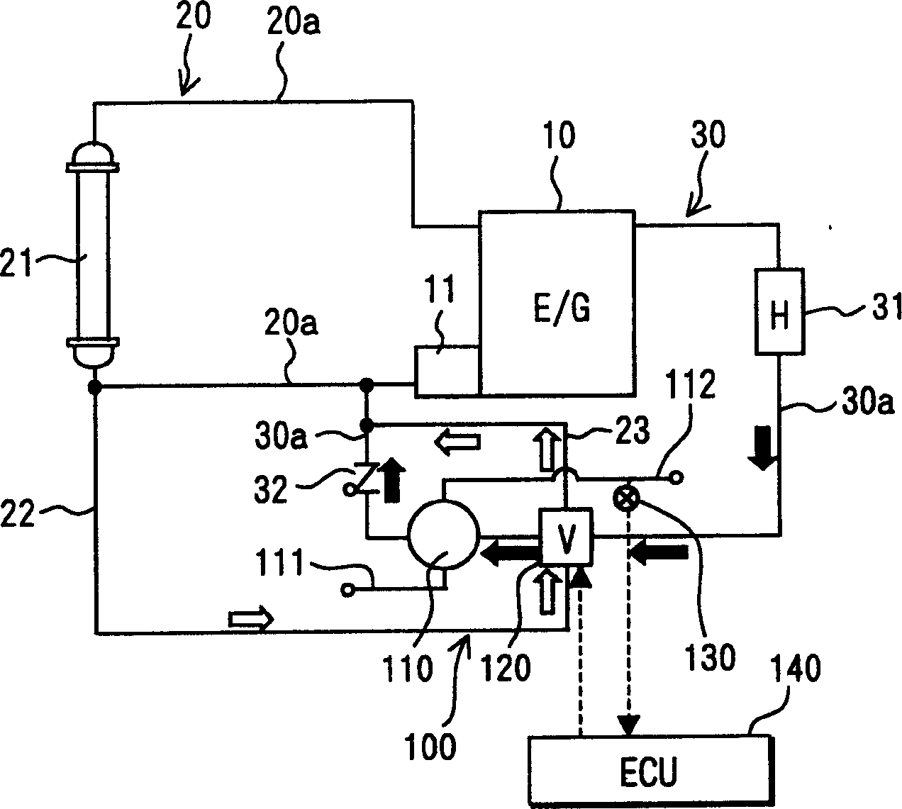
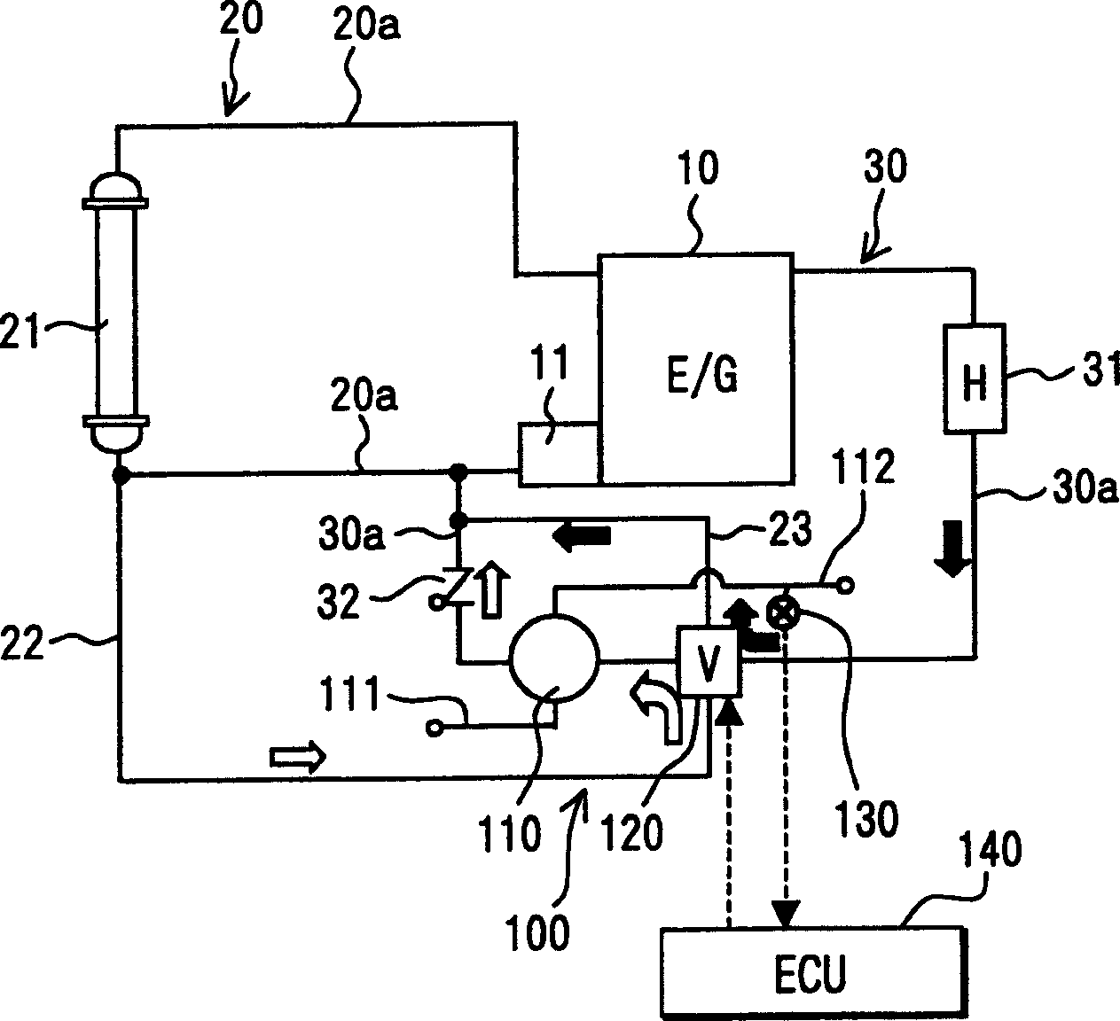
[0017] Refer to the following Figure 1-3 A first embodiment of the present invention is described. The vehicle engine 10 is provided in a cooling water circuit system in which cooling water (coolant) for cooling the vehicle engine 10 flows. The vehicle engine 10 includes an automatic transmission (not shown) provided with a torque converter for operating clutches and various gears of the transmission. Lubricating oil (ATF) is used as a power transmission medium in a torque converter. Cooling water 100 is provided to rapidly increase the temperature of the lubricating oil when the temperature of the lubricating oil is lower than the set temperature after the engine is started, and is also used to cool the lubricating oil to an appropriate temperature during normal operation of the engine.

[0018] The cooling water circuit system of the engine 10 includes a water circuit 20 of the water tank to adjust the temperature of the engine 10 at an appropriate temperature. The water...

no. 2 example

[0036] Refer to the following Figure 4 A second embodiment of the present invention is described. In the second embodiment, a water tank main bypass passage 24 is provided in the cooling water circuit system, through which the cooling water bypasses the water tank 21 . In addition, at the joint portion where the tank water passage 20a at the tank 21 is combined with the tank main bypass passage 24, a temperature controller 26 is provided.

[0037] A branch passage 25 branched from the tank main bypass passage 24 is provided. The refrigerant from the radiator main bypass passage 24 passes through the branch passage 25 and returns to the engine 10 after passing through the oil cooler 110 . A branch bypass circuit 40 is formed by the water tank main bypass passage 24 and the branch passage 25 , so that the refrigerant from the engine 10 returns to the engine 10 through the branch bypass circuit 40 while bypassing the water tank 21 . The branch bypass circuit 40 is the water t...


PUM


Abstract

A cooling water circuit system for an engine, comprising: a water tank bypass passage (30, 40), through which cooling water of the engine bypasses the water tank (21); a heat exchanger (110) installed in the water tank bypass circuit ), heat exchange is performed between the cooling water and the lubricating oil of the automatic transmission; and the water tank downstream passage (22), through which the cooling water from the water tank flows into the heat exchanger. In addition, the flow regulating unit (120, 121) is arranged at the junction of the water tank bypass passage and the water tank downstream passage to adjust the flow rate of the cooling water flowing from the water tank downstream passage to the heat exchanger, and from the water tank side The flow rate of cooling water flowing through the path to the heat exchanger. The flow regulating unit is controlled by a control unit (140) according to the temperature measured by the temperature detecting unit.

Description

technical field [0001] The invention relates to a cooling water circuit system of a vehicle engine, which is suitable for heating and cooling lubricating oil of an automatic transmission mounted on the vehicle. Background technique [0002] In the ordinary cooling water circuit system, an oil heat exchanger is specially set, and the lubricating oil of the automatic transmission flows in this exchanger. When the temperature controller is closed, the engine cooling water flows in this cooling water circuit system (such as JP -A-2002-47935). The heat exchanger realizes the heat exchange between the lubricating oil and the engine cooling water, so as to heat the lubricating oil in the warm-up work after the vehicle engine is started, and cool the lubricating oil in the normal operation of the engine. However, in this heat exchanger, since the cooling water (hot water) in the heater water circuit is used to heat the lubricating oil to fully heat the lubricating oil during the wa...

Claims


Application Information

Patent Timeline
Patent Type & Authority Applications(China)
IPC IPC(8): F01M5/00F01P7/14F01P7/16
CPCF01M5/007F01P7/165F01P2007/146F01P2025/40F01P2037/02F01P2060/045F01P2060/08
Inventor 菅野辰也鱼住信幸高塚道也
Owner DENSO CORP
Why Eureka
Try Eureka