
Method for imaging of pre-stack seismic data

A pre-stack seismic and data technology, applied in seismology, seismic signal processing, preparation of test samples, etc., can solve problems such as undesirable side effects

Inactive Publication Date: 2005-04-27
PGS AMERICA INC
View PDF0 Cites 6 Cited by
  • Summary
  • Abstract
  • Description
  • Claims
  • Application Information

AI Technical Summary

Problems solved by technology

However, it has the undesirable side effect of inhibiting accurate recovery of geometrical deviations

Method used


Image

  • Method for imaging of pre-stack seismic data
  • Method for imaging of pre-stack seismic data
  • Method for imaging of pre-stack seismic data

Examples


no. 1 example

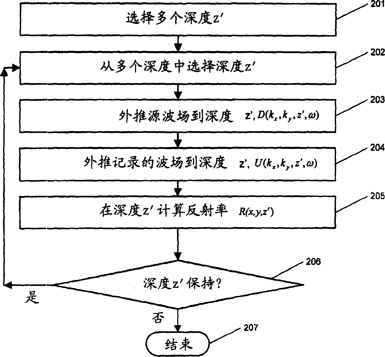
[0129] In step 205, reflectivity R(x, y, z') is calculated at depth z'. Reflectance can be calculated, for example, by equation (21). Reflectance can be calculated as an average of the ratios over all frequencies, as an average over normalized power ratios using pre-whitening, or by least squares. Preferably, the reflectance is calculated by one of the two embodiments of the invention described above. A first embodiment of the present invention, the normalized power ratio with spatially varying pre-whitening factors is discussed with reference to equations (25)-(29) above. A second embodiment of the present invention, the method of least squares, is discussed with reference to equation (33) above.

[0130] In step 206 , it is determined whether any depth z' remains as selected from the plurality of depths selected in step 201 . If the answer is yes, depth z' is maintained and processing returns to step 202 to select the next depth. If the answer is no, then depth z' is not...


PUM


Abstract

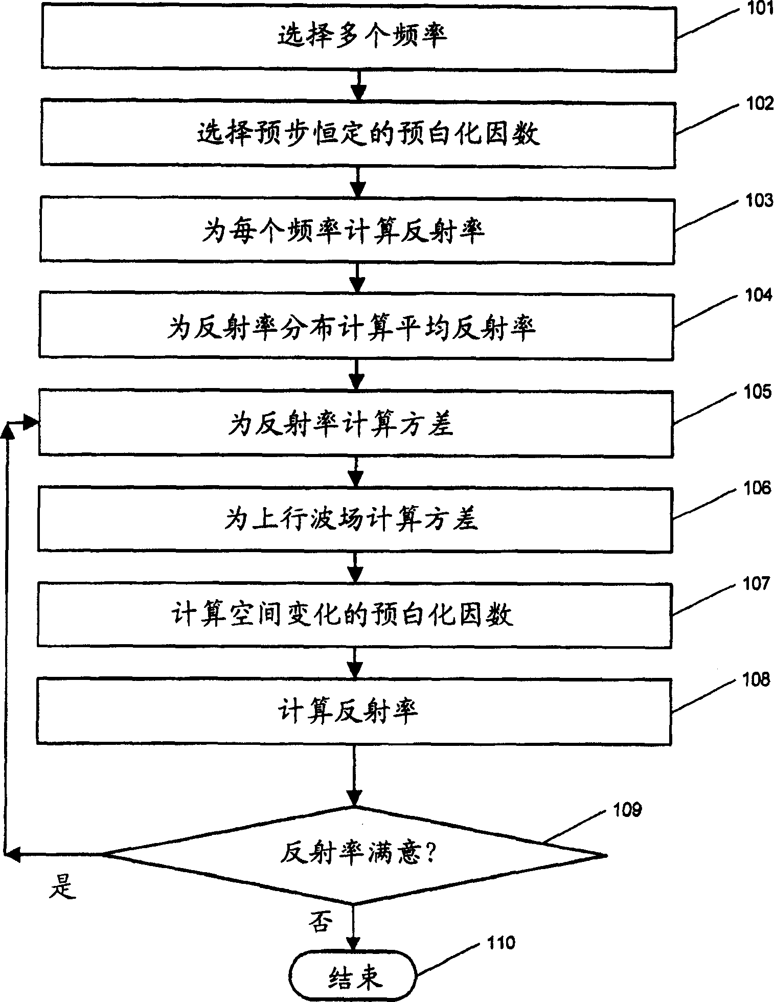
Prestack seismic data is imaged by calculating an individual reflectivity for each frequency in the seismic data. Then, a mean reflectivity is calculating over the individual reflectivities. A variance is calculated for the set of reflectivities versus frequency. A second variance is calculated for the upgoing wavefield, using the mean reflectivity. A spatially varying pre-whitening factor is then calculated, using the variance for the reflectivities and the variance for the upgoing wavefield. A reflectivity is calculated at each location, using the spatially varying pre-whitening factor.

Description

field of invention [0001] The present invention relates generally to the field of geophysical prospecting. More specifically, the present invention relates to the field of seismic data processing. In particular, the invention is a method for imaging seismically migrated prestack seismic data. Background technique [0002] Seismic migration is the process of constructing reflector surfaces that define subsurface formations of interest from recorded seismic data. Thus, the process of migration provides a picture of the formation in depth or time. An attempt is made to account for the positioning (kinematics) and amplitude (dynamics) effects associated with the transmission and reflection of seismic energy from a seismic source to a seismic receiver. Although vertical variations in velocity are the most common, lateral variations are also encountered. These velocity changes are caused by a number of causes including the differentiation and compaction of formations, the upli...

Claims


Application Information

Patent Timeline
Patent Type & Authority Applications(China)
IPC IPC(8): G01N1/28G01V1/00G01V1/28G01V1/32G01V1/36G06K9/00G06K11/06G09G5/00
CPCG01V1/28G01V2210/57
Inventor S·M·凯利
Owner PGS AMERICA INC
Learn More