Flow measuring mechanism of watermeter

A flow measurement and water meter technology, applied in the field of water flow measurement, can solve the problems of low sensitivity of water meters, loss of water resources, large frictional resistance, etc.

Inactive Publication Date: 2005-05-11
朱志军 +1
View PDF0 Cites 3 Cited by
  • Summary
  • Abstract
  • Description
  • Claims
  • Application Information

AI Technical Summary

Problems solved by technology

The problem is: in these existing water meters, the water flowing in from the water inlet of the water meter flows towards the diversion hole along the direction perpendicular to the axis of the wing wheel
As a result, the friction resistance increases, and the sensitivity of the water meter is not high; the support of the wing wheel sha

Method used


Image

  • Flow measuring mechanism of watermeter
  • Flow measuring mechanism of watermeter
  • Flow measuring mechanism of watermeter

Examples


Embodiment 1

[0015] Embodiment 1 (in conjunction with Figure 1~5 )

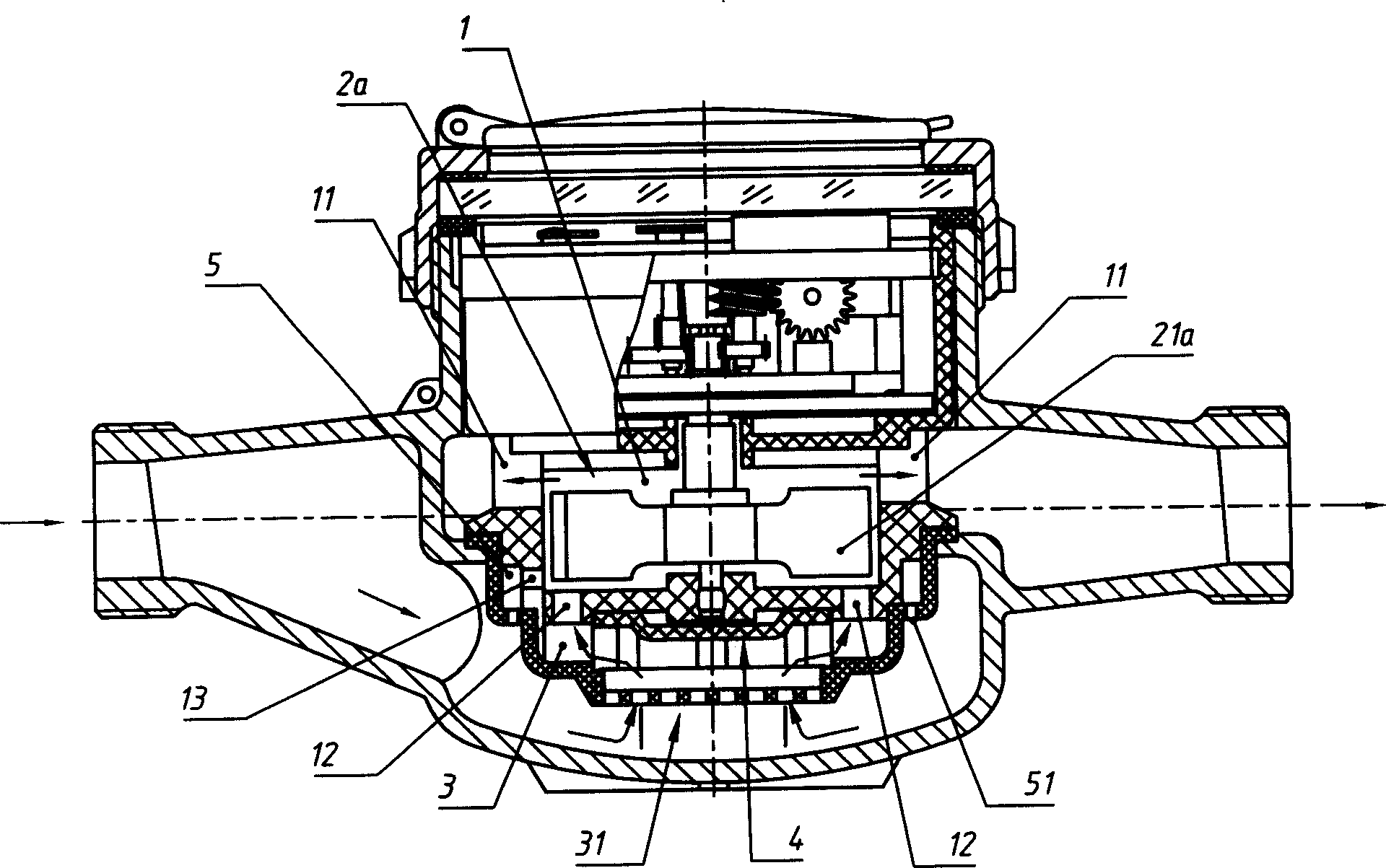
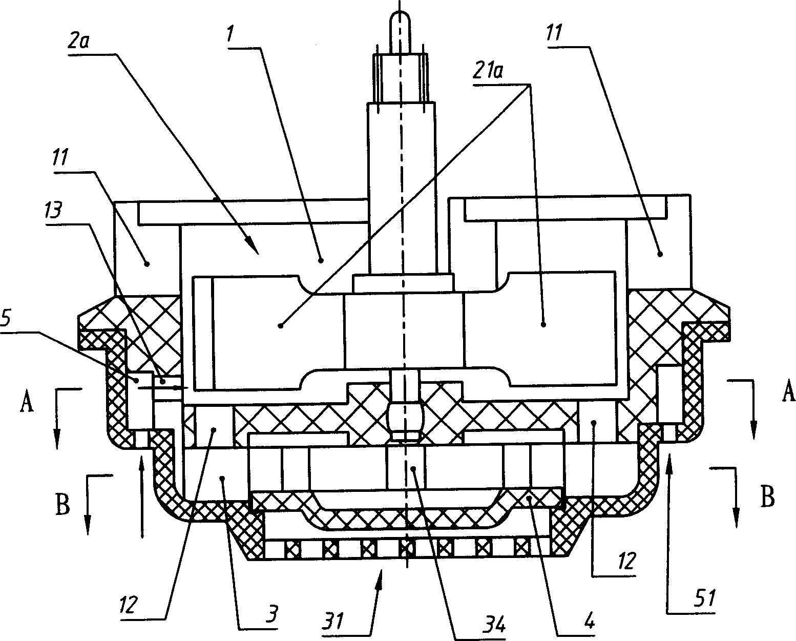
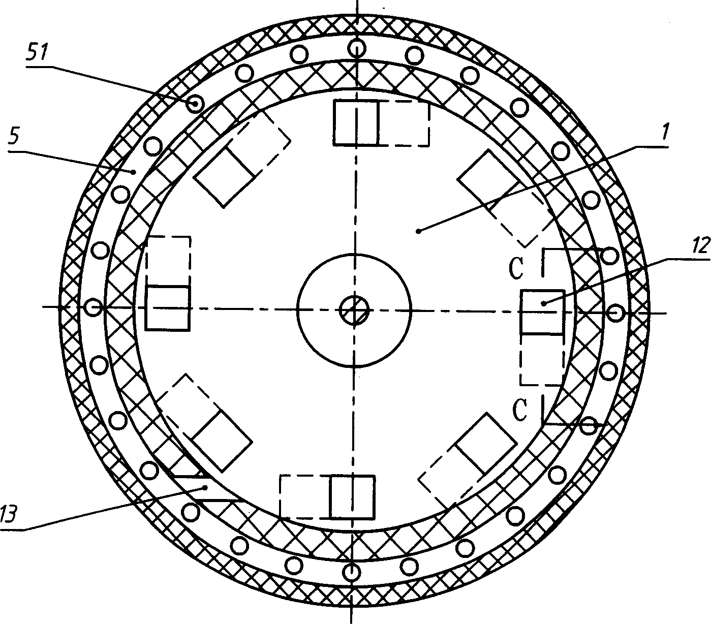
[0016] A flow measuring mechanism of a water meter, which includes a measuring cavity 1 with a water outlet 11 on the upper part and a wing wheel in the measuring cavity 1, and several diversion holes 12 for guiding the water flow to the wing wheel and the measuring cavity 1 connected. This mechanism is installed in the lower part of the water meter housing, and the water outlet 11 of the measuring chamber 1 communicates with the water outlet of the water meter; the metering mechanism for displaying the accumulated flow is installed on the upper part of the water meter housing. On the top of the wheel shaft of the wing wheel, there is a transmission gear connected with the metering mechanism to drive its metering. In this example mechanism, the impacted surface of the blade 21a of the wing wheel 2a is a plane, which is parallel to the wheel axis of the wing wheel 2a. There are six to fourteen diversion holes 12 . The...

Embodiment 2

[0017] Embodiment 2 (with reference to Figure 1~5 , combine Image 6 , 7 )

[0018] The structure of this example is basically the same as that of Embodiment 1, so the same parts will not be described again. There is one difference in the structure from Embodiment 1, that is, the impacted surface of the blade 21b of the wing wheel 2b is also a plane, but there is an upward axial component force on the wing wheel 2b between the plane and the wheel shaft of the wing wheel 2b. The included angle is between 5° and 20°. Obviously, the included angle still needs to be determined in combination with other conditions. In this example, 10° is taken. Under the condition that other conditions and structures are the same, the mechanism of this example is assembled in a water meter that requires an axial component force greater than that of Example 1.

[0019] The technical characteristics in the above-mentioned examples have played an important role in improving the wear resistance ...


PUM


Abstract

A measuring mechanism of flow rate consists of measuring cavity with water outlet at its top, vane wheel in the cavity and a numbers of flow guide holes for guiding water flow to vanewheel. It is featured as setting all flow guide holes at bottom of measuring cavity in annular form uniformly by utilizing vane wheel shaft of a centre, setting a non-return by utilizing vane wheel shaft as a centre, setting a non-return disc on water inlet top cover of water collector and setting one or four small flow guide hole niterlinked to small water collector being isolated to said water collector at side wall of measuring cavity.

Description

technical field [0001] The invention belongs to the field of water flow measurement, in particular to a water meter with a pipe diameter of 25mm (1") or below. Background technique [0002] At present, water meters for measuring domestic water for urban and rural residents generally use water meters below DN 25mm (1″). In some special occasions, such as direct drinking water, smaller water meters are also used. Most of them use rotor type Water meter. The structure of the water meter is that a metering mechanism for displaying the accumulated flow is installed on the upper part of the water meter housing, and a rotor-type measuring mechanism is installed on the lower part. The measuring mechanism includes a measuring chamber and a wing wheel for measuring water flow in the measuring chamber The wing wheel has a number of uniformly distributed blades whose force-bearing surface is parallel to the axis of the wing wheel; there is a transmission gear connected with the metering...

Claims


Application Information

Patent Timeline
IPC IPC(8): G01F1/06G01F1/08
Inventor 朱志军朱永强
Owner 朱志军
Why Eureka
Try Eureka