Engine

A technology for engines and driven shafts, which is applied to engine components, machines/engines, motor vehicles, etc., and can solve problems such as difficult maintenance of driving gears and lengthening of crankshafts

Inactive Publication Date: 2005-05-11
YAMAHA MOTOR CO LTD
View PDF1 Cites 0 Cited by
  • Summary
  • Abstract
  • Description
  • Claims
  • Application Information

AI Technical Summary

Problems solved by technology

[0003] However, when the above-mentioned plurality of driving gears are only arranged in parallel on the crankshaft, in order to securely attach the driving gears to the crankshaft, it is necessary to increase the thickness of each driving gear in the axial direction. long length problem
In addition, when the above-mentioned drive gears are mounted by press-fitting, there is also a concern that maintenance such as replacement of these drive gears becomes difficult.

Method used


Image

  • Engine
  • Engine
  • Engine

Examples


Embodiment Construction

[0031] Embodiments of the present invention will be described below based on the drawings.

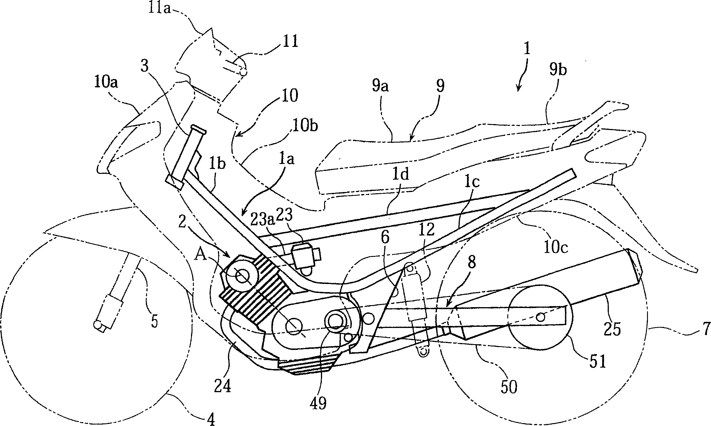
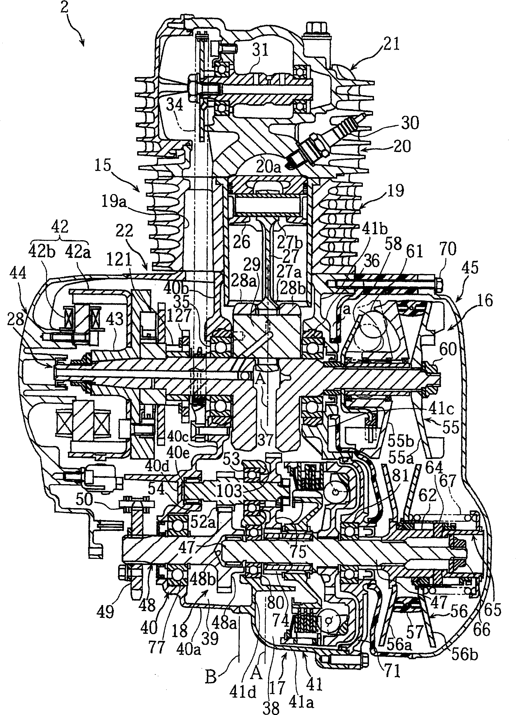
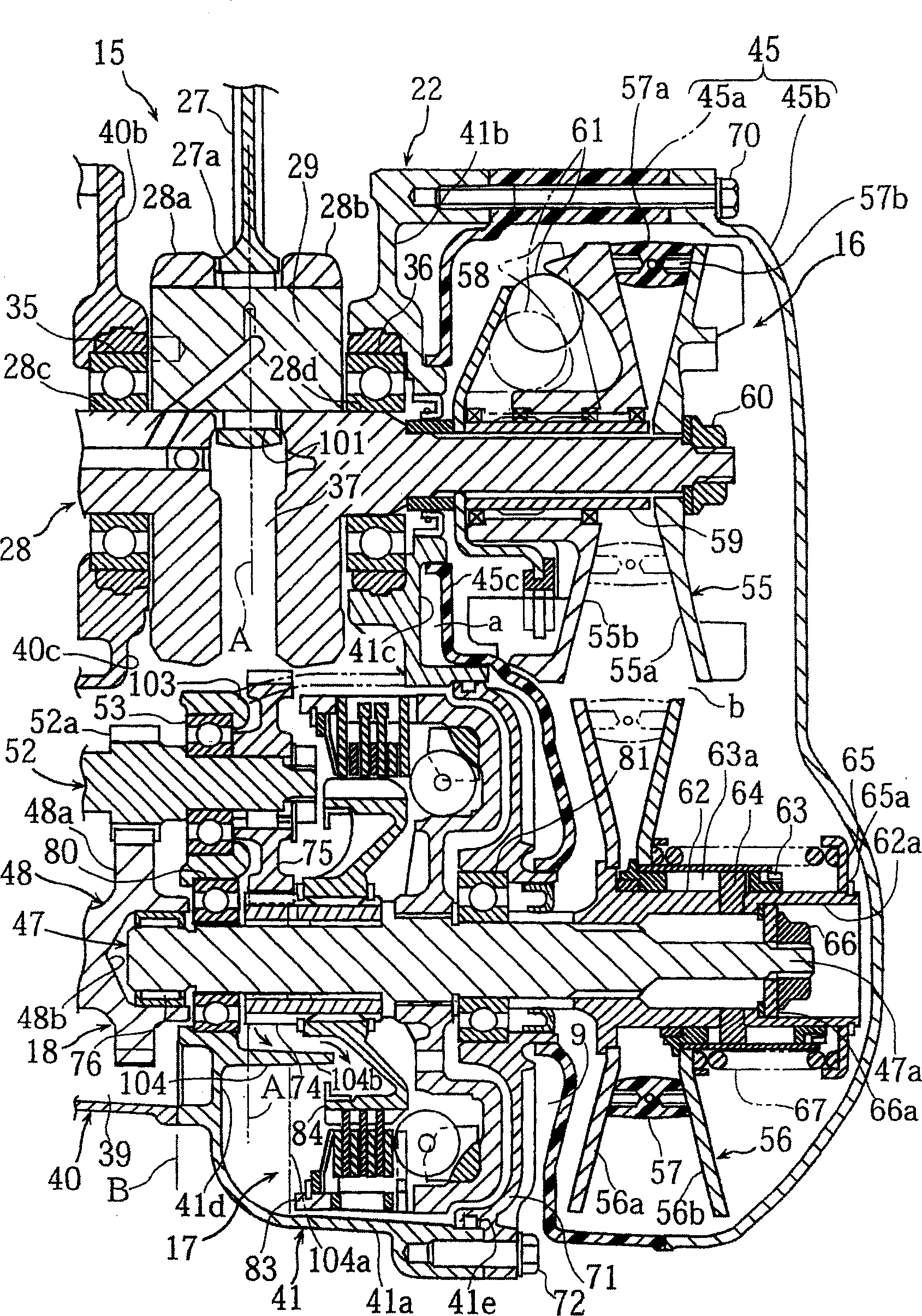
[0032] Figure 1 to Figure 15 is a diagram for explaining a motorcycle engine according to an embodiment of the present invention, figure 1 It is the left side view of the motorcycle equipped with the engine of this embodiment, figure 2 It is a sectional top view showing the engine in the unfolded state ( Figure 6 II-II line profile), image 3 It is a cross-sectional top view of the continuously variable transmission mechanism and the centrifugal clutch mechanism of the engine, Figure 4 , Figure 5 are the right side view and left side view of the engine, Figure 6 It is a right side view with the engine's continuously variable transmission mechanism and centrifugal clutch mechanism removed, Figure 7 is the right side view of the crankcase, Figure 8 is the sectional top view of the crankcase ( Figure 5 VIII-VIII line profile), Figure 9 It is a cross-sectional top view o...


PUM


Abstract

The present invention provides an engine, between the crankshaft and the first and second driven shafts, through the first drive gear and the second drive gear on the side of the crankshaft and the first drive gear on the side of the first and second driven shafts. A driven gear and a second driven gear transmit rotational force, the above-mentioned first driving gear is fixedly installed on the above-mentioned crankshaft, and at the same time, the above-mentioned second driving gear is overlapped with the mated portion of the first driving gear and detachably fit on the first drive gear, the transmission of the rotational force between the above-mentioned crankshaft and the above-mentioned first driven shaft is between the above-mentioned first drive gear and the above-mentioned first driven The gears are directly connected to each other, and the transmission of the rotational force between the crankshaft and the second driven shaft is performed between the first driving gear and the second driven gear via the second driving gear.

Description

technical field [0001] The present invention relates to an engine, which utilizes a first drive gear and a second drive gear installed on a crankshaft to respectively drive a first driven shaft and a second driven shaft, such as a lubricating oil pump shaft, a balancer shaft, or , for example, the crankshaft is rotationally driven by the kicker shaft via the above-mentioned first drive gear. Background technique [0002] For example, in a motorcycle engine, generally, a plurality of drive gears mounted on a crankshaft, for example, rotate and drive a lubricating oil pump and a balancer shaft (for example, refer to Japanese Patent Application Laid-Open No. 8-189323). In this case, each of the above-mentioned driving gears is set to have an outer diameter corresponding to the purpose of the driven member. For example, since the lubricating oil pump is driven at a speed that decelerates the rotation of the engine, and the balancer shaft is driven at the same rotational speed a...

Claims


Application Information

Patent Timeline
IPC IPC(8): F02B61/02F02B75/02F02B75/16F02F7/00F16H1/06
CPCF02B75/16F02B61/02F02B2075/027F02B2275/20
Inventor 大石明文石田洋介
Owner YAMAHA MOTOR CO LTD
Why Eureka
Try Eureka