Auxiliary water heating stove for civil range

A water heating furnace and auxiliary furnace technology, which is applied to household furnaces/stoves, applications, household heating, etc., can solve the problems of wasting energy and low utilization rate of heat, and achieve equipment and space saving, fuel energy saving, and simple structure Effect

Inactive Publication Date: 2005-05-18
及永庆
View PDF0 Cites 0 Cited by
  • Summary
  • Abstract
  • Description
  • Claims
  • Application Information

AI Technical Summary

Problems solved by technology

The disadvantage of this heating method is that the heat energy is dissipated w...

Method used


Image

  • Auxiliary water heating stove for civil range
  • Auxiliary water heating stove for civil range

Examples


Embodiment Construction

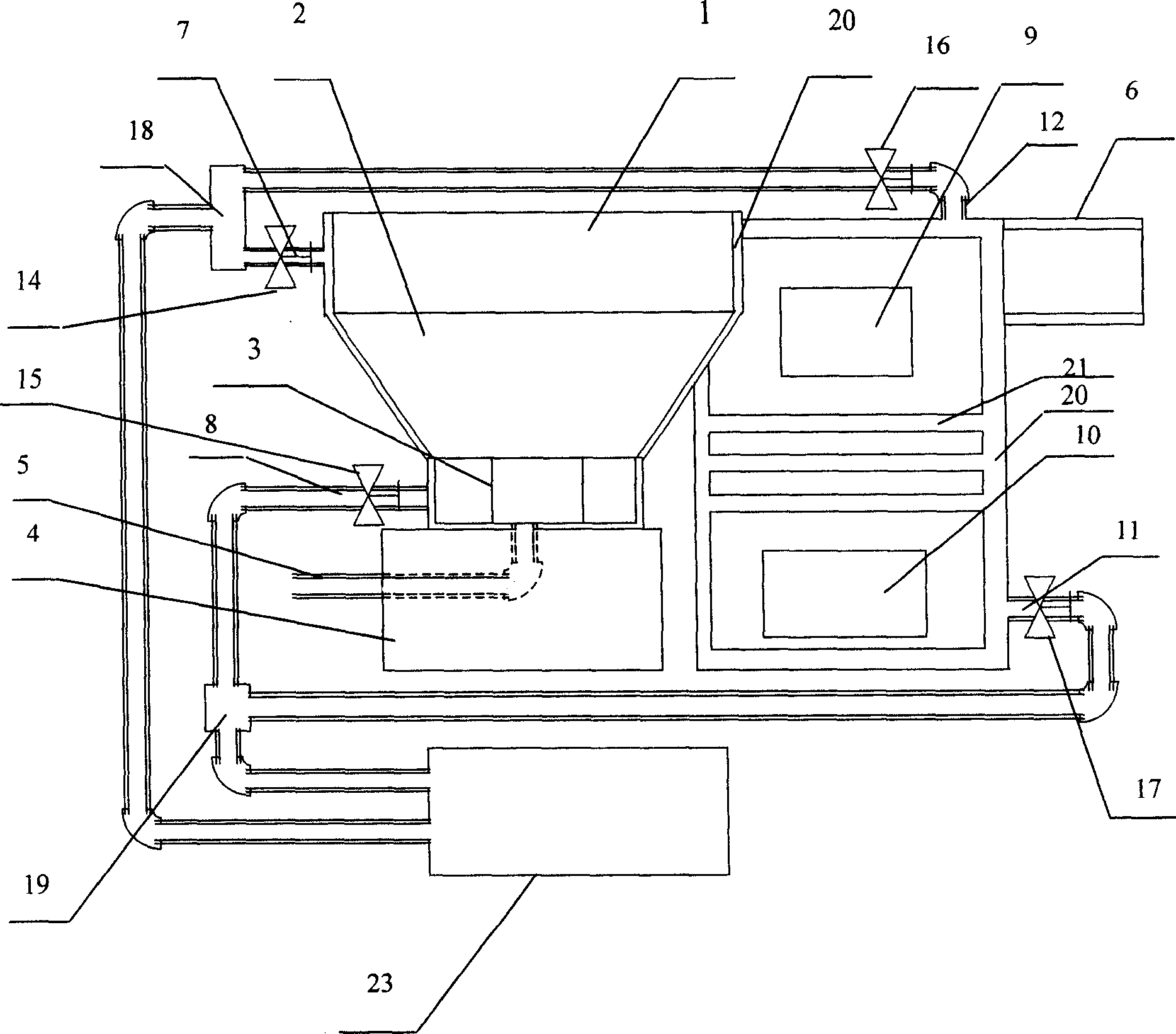
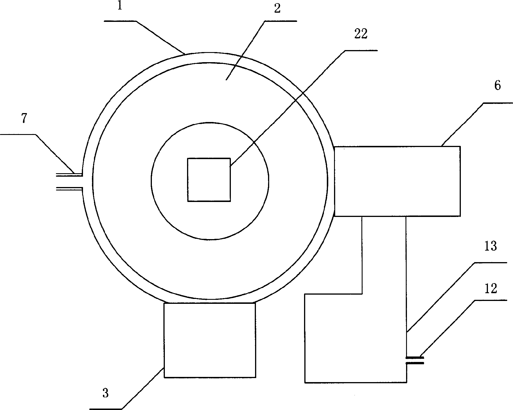
[0038] The following is attached with the manual Figure 1 to Figure 2 The structural features and working principle of the auxiliary water heating stove for civil stoves described in the present invention are further explained:

[0039] Such as figure 1 As shown, the present invention includes: a main furnace and an auxiliary furnace respectively arranged on the left and right sides. The main furnace includes: the main furnace pot seat 1 located on the upper part thereof, the furnace 2 located at the lower part of the main furnace pot seat 1, the stove door 3 located under the furnace hearth 2, the furnace base 4 located under the stove door 3, and the left side of the furnace base 4 Air outlet 5 is set on the face. Such as figure 1 As shown, the main furnace outlet pipe 7 and the main furnace water inlet pipe 8 are respectively installed on the upper left side and the lower right side of the main furnace. A main furnace outlet pipe valve 14 and a main furnace water inlet...


PUM


Abstract

The present invention relates to heating apparatus, and especially one auxiliary water heating stove for civil range suitable for use of dispersively living peasants. The auxiliary water heating stove includes main stove, auxiliary stove, water inlet pipe, water outlet pipe, smoke pipe, heating fins, etc. It has several functions of cooking, heating hotbed and heating, and its afterheat is utilized fully. The present invention has simple structure and convenient installation, and may be used in replacing small boiler.

Description

technical field [0001] The invention relates to heating equipment, in particular to a civil stove auxiliary water heating stove suitable for rural households living scatteredly. Background technique [0002] In northern my country, the winter is cold and the temperature is low. People’s living quarters, hotels, restaurants and other places need to use heating equipment for heating, such as a plumbing circulation system that usually uses boilers connected to indoor radiators. However, this heating system is not suitable for farmers living in scattered vast rural areas. Heating is done by burning stoves in the north. The shortcoming of this heating method is that heat energy is dissipated without recycling, the utilization rate of heat is low, and a lot of energy is wasted in vain. Contents of the invention [0003] The purpose of the present invention is to provide an auxiliary water heating stove for civil stoves, which can be used for multiple purposes, so that the farm...

Claims


Application Information

Patent Timeline
IPC IPC(8): F24B7/00F24B9/00
Inventor 及永庆
Owner 及永庆
Why Eureka
Try Eureka