Continuous steel making process for iron ore

A technology of technology and steelmaking furnace, applied in the field of continuous production of molten steel with iron ore, can solve the problems of no progress and achieve the effect of saving equipment and infrastructure investment, saving equipment and infrastructure investment, and simple and orderly logistics

Inactive Publication Date: 2010-03-10
LAIWU IRON & STEEL GRP
View PDF9 Cites 15 Cited by
  • Summary
  • Abstract
  • Description
  • Claims
  • Application Information

AI Technical Summary

Problems solved by technology

Cyclone furnace smelting reduction has only been tested in the middle and has not made any progress so far

Method used


Image

  • Continuous steel making process for iron ore

Examples


Embodiment 1

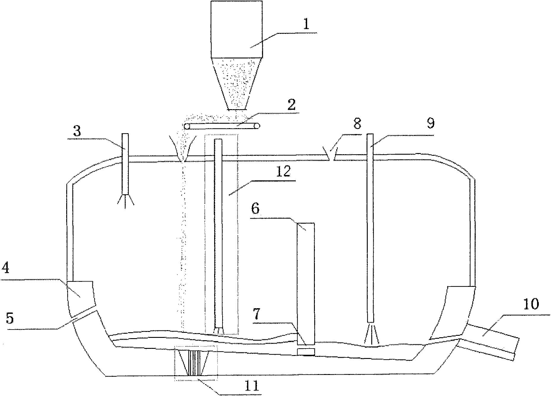
[0042] The continuous steelmaking equipment of the present invention comprises: fine ore conveying bed 1, feeding device 2, secondary combustion oxygen lance 3 in gas phase zone, continuous steelmaking furnace 4, slag outlet 5 in reduction zone of continuous steelmaking furnace, continuous steelmaking furnace Furnace retaining wall 6, continuous steelmaking furnace molten iron channel 7, flux charging port 8 in decarburization zone, oxygen lance 9 in decarburization zone, steel tapping port 10; continuous steelmaking furnace 4 has a rectangular cross section, including reduction zone and oxidation zone Decarburization zone, longitudinal section as figure 1 shown. Continuous steelmaking furnace 4 includes refractory system, water cooling system, waste gas treatment and waste heat recovery system.

[0043] Above the continuous steelmaking furnace, there is a conveying bed equipment 1, which is connected to the continuous steelmaking furnace 4 through the feeding device 2, and t...

Embodiment 2

[0050] Mix iron concentrate powder with some iron-containing lump ore, limestone, and dolomite. Their ratio is determined according to the composition of the slag in the smelting process of these materials and through material balance calculation. Generally, the alkalinity of the slag is taken 1~1.5, Al 2 o 3 5%~18%, MgO 5%~10%, FeO 10% or less. Coal or coke powder is then also added to these mixes. The amount of coal powder or coke powder is determined by 500-1200kg / ton of iron. Then the mixed material is fed into the continuous steelmaking furnace through the feeding device 2 by means of a screw feeder. A molten iron pool with a thickness of 100-800mm is reserved in advance in the continuous steelmaking furnace 4, and the iron concentrate powder, coal powder and flux quickly form a liquid mixture slag layer, and direct reduction of iron oxides occurs in the slag layer.

[0051] At the same time, industrial oxygen is blown into the slag layer through the secondary combus...

Embodiment 3

[0055] Mix the finely ground and pre-reduced iron ore powder with limestone and dolomite, and their ratio is determined according to the composition of the slag in the smelting process of these materials and through material balance calculation. Generally, the alkalinity of the slag is 1~1.5, Al 2 o 3 5%~18%, MgO 5%~10%, FeO 10% or less. Others are with embodiment 2.


PUM

PropertyMeasurementUnit
thicknessaaaaaaaaaa
thicknessaaaaaaaaaa

Abstract

The invention discloses a continuous steel making process for iron ore, which comprises the following steps: by adopting a direct carbon reduction mode of liquid iron oxide, adding the iron ore or pre-reduced ore powder into slag iron bath in advance, dissolving the iron ore or the pre-reduced ore powder to form slag, then using carbon to quickly reduce the liquid iron oxide to obtain liquid iron,next blowing oxygen at the other end of a furnace to remove the carbon so as to obtain molten steel, namely realizing iron mineral addition and molten steel production in the same furnace. CO produced in the reduction reaction is mainly used for secondary combustion to compensate the heat required by the reduction reaction, and the waste gas is used for pre-heating and pre-reducing (the iron mineral can be pre-reduced in weak reducing atmosphere). The process makes full use of characteristic of high direct carbon reduction speed of the liquid iron oxide, has high production rate and low ton steel-carbon consumption, saves equipment and capital construction investment, fully simplifies material flow, avoids temperature loss of the liquid iron during transportation, and is easy to realize continuous production and automatic control.

Description

technical field [0001] The invention relates to a steel production process, in particular to a process for continuously producing molten steel with iron ore. Background technique [0002] At present, the most important iron and steel production process (long process) is to obtain molten steel from iron ore, which needs to go through four main process links: sintering (or pelletizing), coking, blast furnace ironmaking, and converter steelmaking, and there are many auxiliary process links. The reduction of more than 70% of iron ore in blast furnace ironmaking is indirect reduction, which is a gas-solid reaction, and the blast furnace is required to maintain good air permeability. Blast furnace use, that is, through the sintering (or pelletizing) process. The material handling capacity of sintering (or pelletizing) accounts for about the second place in iron and steel complexes (after ironmaking production), and the energy consumption ranks third after ironmaking and steel rol...

Claims


Application Information

Patent Timeline
Patent Type & Authority Applications(China)
IPC IPC(8): C21B13/00
Inventor 张胜生董杰周勇
Owner LAIWU IRON & STEEL GRP
Why Eureka
Try Eureka