Direct steel making technique by reducing iron ore with gas

A direct and process technology, applied in the field of iron ore gas reduction to directly produce molten steel, can solve problems such as no progress, and achieve the effects of saving equipment and infrastructure investment, simplifying logistics, and simple and orderly logistics

Inactive Publication Date: 2010-03-31
LAIWU IRON & STEEL GRP
View PDF9 Cites 17 Cited by
  • Summary
  • Abstract
  • Description
  • Claims
  • Application Information

AI Technical Summary

Problems solved by technology

Cyclone furnace smelting reduction has only been tested in the middle and has not made any progress so far

Method used


Image

  • Direct steel making technique by reducing iron ore with gas

Examples


Embodiment 1

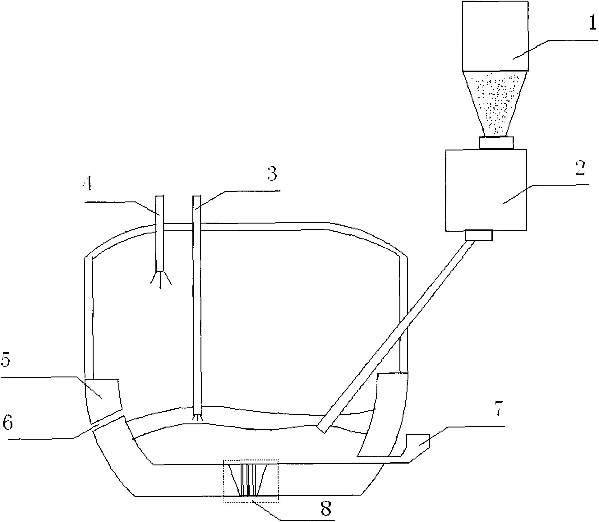
[0039] The direct steelmaking equipment of the present invention comprises: a fine ore conveying bed (1), a feeding device (2), a reducing gas spray gun (3), a secondary combustion oxygen lance in the gas phase zone (4), a direct steelmaking furnace (5 ), direct steelmaking furnace slag outlet (6), direct steelmaking furnace steel outlet (7); direct steelmaking furnace (5) is a barrel-shaped furnace, and the longitudinal section is as figure 1 shown. The direct steelmaking furnace (5) includes a refractory system, a water cooling system, waste gas treatment and waste heat recovery system.

[0040] There is a conveying bed equipment (1) above the direct steelmaking furnace, and the conveying bed equipment (1) is connected with the direct steelmaking furnace (5) through a feeding device (2); the reducing gas spray gun (3) is inserted into the slag area, and the gas phase The secondary combustion oxygen lance (4) in the zone is inserted into the gas phase space above the direct ...

Embodiment 2

[0047] Mix iron concentrate powder with some iron-containing lump ore, limestone, and dolomite. Their ratio is determined according to the composition of the slag in the smelting process of these materials and through material balance calculation. Generally, the alkalinity of the slag is taken 1~1.5, Al 2 o 3 5%~18%, MgO 5%~10%, FeO 10% or less. Then the mixed material is loaded into the direct steelmaking furnace 5 through the screw feeder 2 . A molten iron pool with a thickness of 100-800 mm is reserved in the direct steelmaking furnace 5 in advance, and the iron concentrate powder and flux quickly form a liquid mixture slag layer. Furnace gas reduces FeO-containing slag to obtain molten steel with a carbon content of less than 1.3%.

[0048] In the upper space of the direct steelmaking furnace, the reduction reaction produces a large amount of CO, and the water-cooled oxygen lance 4 blows oxygen, and the secondary combustion of CO provides part of the heat for the reduc...

Embodiment 3

[0051] Mix the finely ground and pre-reduced iron ore powder with limestone and dolomite, and their ratio is determined according to the composition of the slag in the smelting process of these materials and through material balance calculation. Generally, the alkalinity of the slag is 1~1.5, Al 2 o 3 5%~18%, MgO 5%~10%, FeO 10% or less. Others are with embodiment 2.


PUM

PropertyMeasurementUnit
thicknessaaaaaaaaaa

Abstract

The invention discloses a direct steel making technique by reducing iron ore with gas, comprising: firstly, adding iron ore and prereducing mineral powder into an iron slag bath, dissolving the iron ore or the prereducing mineral powder into the slag, blowing reducing gas into the slag layer, reducing the slag containing FeO, and obtaining molten steel with carbon content less than 1.3%. CO generated in the reduction reaction is mainly used for secondary combustion to compensate heat energy needed by the reduction reaction, and the exhaust gas is used for prewarming and prereducing (the iron mineral is prereduced in very weak reducing atmosphere). The technique fully utilizes the features that the reducing gas will not carburize and siliconize the molten steel, and implements the production of molten steel from iron mineral only by one direct steel-smelting furnace. The technique of the invention has advantages of high yield, low energy consumption per ton steel, save of equipment andconstruction investment, sufficient simplification of physical distribution, and the technique avoids temperature loss of the molten iron in transport process, and easily implements continuous production and automation control.

Description

technical field [0001] The invention relates to a steel production process, in particular to a process for directly producing molten steel through gas reduction of iron ore. Background technique [0002] At present, the most important iron and steel production process (long process) is to obtain molten steel from iron ore, which needs to go through four main process links: sintering (or pelletizing), coking, blast furnace ironmaking, and converter steelmaking, and there are many auxiliary process links. The reduction of more than 70% of iron ore in blast furnace ironmaking is indirect reduction, which is a gas-solid reaction, and the blast furnace is required to maintain good air permeability. Blast furnace use, that is, through the sintering (or pelletizing) process. The material handling capacity of sintering (or pelletizing) accounts for about the second place in iron and steel complexes (after ironmaking production), and the energy consumption ranks third after ironmaki...

Claims


Application Information

Patent Timeline
Patent Type & Authority Applications(China)
IPC IPC(8): C21B13/00C21C5/00
CPCY02P10/143
Inventor 张胜生董杰周勇
Owner LAIWU IRON & STEEL GRP
Why Eureka
Try Eureka