Electric vacuum cleaner

A vacuum cleaner and electric technology, applied in the direction of vacuum cleaners, cleaning equipment, household appliances, etc., can solve the problems of sudden closing, impact of the main body 15, etc., and achieve the effect of high performance.

Inactive Publication Date: 2005-05-25
PANASONIC CORP
View PDF2 Cites 0 Cited by
  • Summary
  • Abstract
  • Description
  • Claims
  • Application Information

AI Technical Summary

Problems solved by technology

[0006] But in the structure of above-mentioned existing electric vacuum cleaner, because the rotation center of described dust collection chamber cover 16 is as Figure 14 As shown in , it is roughly located on the upper part of the main body 15. Therefore, when the dust bag cover 16 is opened to replace the dust bag, if the dust bag cover 16 is accidentally touched , or under the action of heavy objects such as dust suction pipes installed on the dust collection chamber cover 16, the dust collection chamber cover 16 may be slammed shut
At this time, since the rotation center of the dust collection chamber cover 16 is approximately at the upper part of the main body 15, when the dust collection chamber cover 16 is closed, the front end of the dust collection chamber cover 16 is mostly at a height lower than the rotation center. Therefore, when the dust collection chamber cover 16 is about to be closed, the dust collection chamber cover 16 has considerable kinetic energy, and there is a problem that it will cause considerable impact to the main body 15.
[0007] In addition, if Figure 15 As shown in , the dust collection chamber cover 16 rotates around the center of the moving wheel 14, although the front end of the dust collection chamber cover 16 may be at a height higher than the center of rotation when the dust collection chamber cover 16 is closed However, since the electric fan 12 is located inside the dust chamber cover 16, if the weight of the electric fan 12 is added, the dust chamber cover 16 also has a considerable weight when it is about to be closed. Kinetic energy, so there is also the problem of causing considerable impact on the main body 15

Method used


Image

  • Electric vacuum cleaner
  • Electric vacuum cleaner
  • Electric vacuum cleaner

Examples


Embodiment 1

[0035] first pass Figure 1 to Figure 6 The first embodiment of the present invention will be described.

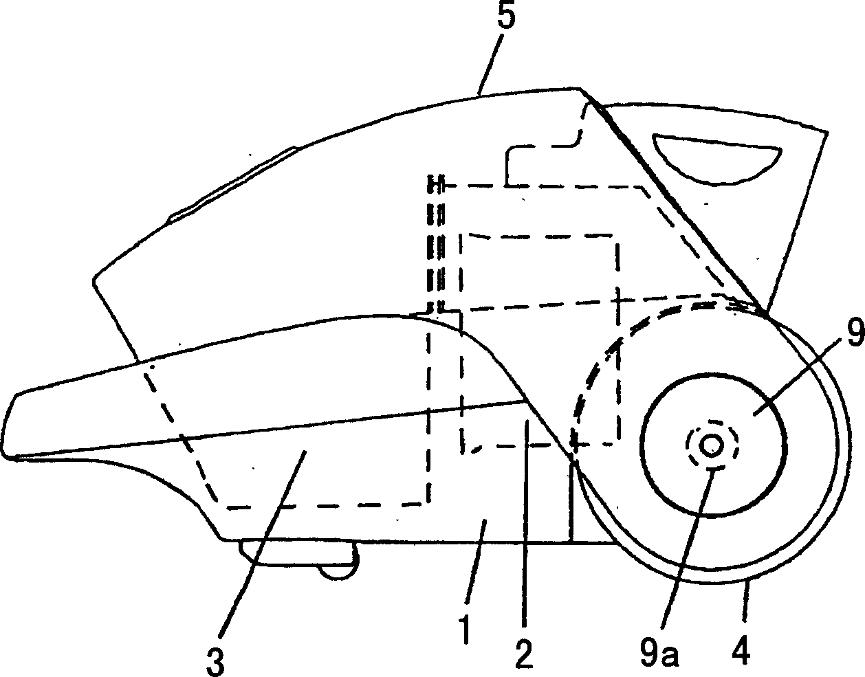
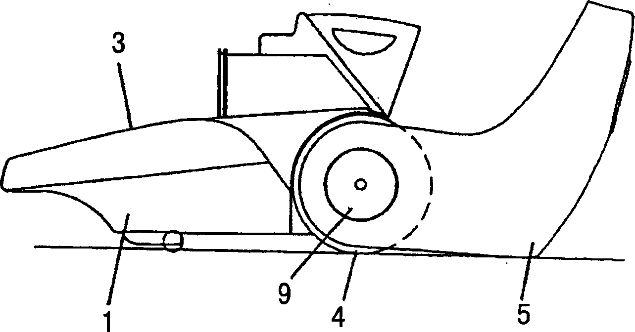
[0036] figure 1 Among them, the inside of the main body 1: there is an electric fan 2 for attracting dust, and a dust collection chamber 3 for collecting dust connected with the suction head for attracting dust, and the walking of the main body 1 is provided at the bottom of the rear Device is mobile wheel 4. The dust collection chamber cover 5 covering the dust collection chamber 3 can rotate around the same center as the rotation center of the moving wheel 4 .

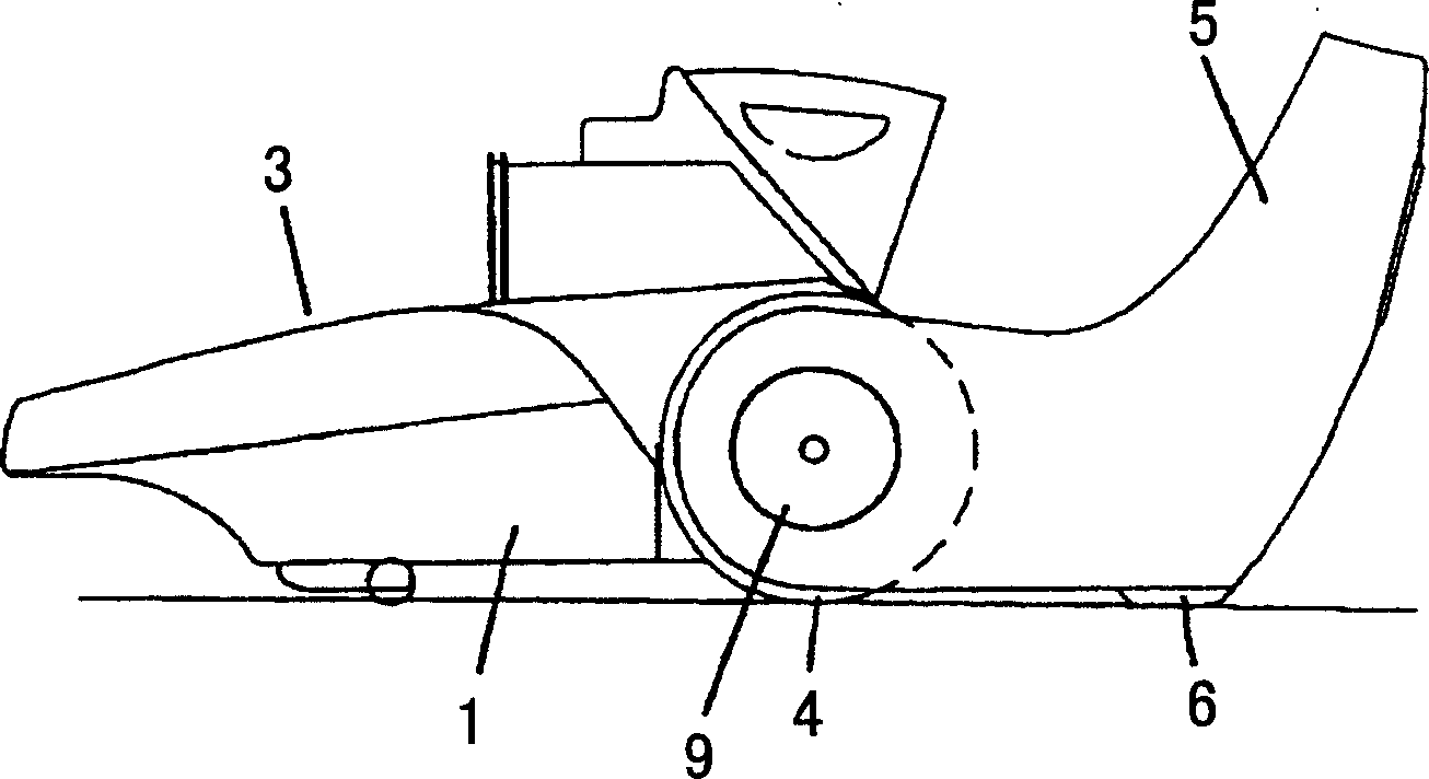
[0037] In addition, in Figure 3 ~ Figure 5 Among them, 6 is a shock absorbing part arranged at the position where the dust collection chamber cover 5 is in contact with the ground when it is rotated, and 7 is a shock absorbing part arranged at the position where the dust collection chamber cover 5 is in contact with the ground when it is rotated. Approximately parallel surfaces at the point of contact. In...

Embodiment 2

[0044] Use below Figure 7 ~ Figure 13 A second embodiment of the present invention will be described. Here, the same components as those in the above embodiment are given the same symbols, and their descriptions are omitted.

[0045] The part 10 is a side protrusion of the dust chamber cover provided near the rotating part of the dust chamber cover 5 . The component 11 is a protrusion on the side of the moving wheel cover, and is provided at a position capable of contacting the protrusion 10 on the side of the dust collection chamber cover located inside the moving wheel cover 9 . When the dust collection chamber cover 5 rotates, the dust collection chamber cover side protrusion 10 and the moving wheel cover side protrusion 11 contact each other, thereby preventing the dust collection chamber cover 5 from further rotating. Additionally, if Figure 13 As shown in , the dust chamber cover side protrusion 10 is also pushed inward by the moving wheel cover side protrusion 11 t...


PUM


Abstract

An object of the present invention is to provide an electric vacuum cleaner capable of providing high usability in opening and closing a dust collection chamber cover. The electric vacuum cleaner of the present invention comprises: an electric blower fan (2) for attracting dust; a dust collection chamber (3) for collecting the inhaled dust; A dust chamber; a main body (1) with an electric blower inside; and a freely rotatable moving wheel (4) that acts as a running device for the main body. Wherein, the rotation center of the dust collection chamber cover is the same as the rotation center of the moving wheel; when the dust collection chamber cover covers the dust collection chamber, the front end part of the front part of the dust collection chamber cover is located above the rotation center of the dust collection chamber cover . In this way, when the dust collection chamber cover is about to be closed, the dust collection chamber cover will not have a strong momentum, so the problem of causing a strong impact on the main body can be solved, thereby providing a new method for opening and closing the dust collection chamber cover. An electric vacuum cleaner with high usability during closing.

Description

technical field [0001] The present invention relates to an electric vacuum cleaner used in common households, and more particularly relates to the improvement of the performance of its dust collecting parts. Background technique [0002] First describe the existing electric vacuum cleaner below. [0003] like Figure 14 As shown in , the existing electric vacuum cleaner includes: an electric fan 12 for attracting dust; a dust collection chamber 13 which is connected with the suction head for attracting dust; a main body 15; and a dust chamber cover 16 for covering the dust chamber 13 (for an example thereof, refer to Japanese Patent Laid-Open No. 1-314529). [0004] In addition, in Figure 15 The existing electric vacuum cleaner shown in is provided with: a dust collection chamber 13 that communicates with the suction head that attracts dust and is used to catch dust; a main body 15 with moving wheels 14 hidden in the rear bottom; 13, an electric fan 12 for attracting dus...

Claims


Application Information

Patent Timeline
Patent Type & Authority Applications(China)
IPC IPC(8): A47L9/00A47L5/00
Inventor 山本雅史
Owner PANASONIC CORP
Why Eureka
Try Eureka