Supercharge Your Innovation With Domain-Expert AI Agents!

Tolerance deviation compensation element

A component and support component technology, applied in the field of span devices, can solve problems such as metal plate deformation, roof shell application, and high cost

Inactive Publication Date: 2010-12-08
SUDDEUTE ALUMINUM MANUFAKTUR
View PDF4 Cites 0 Cited by
  • Summary
  • Abstract
  • Description
  • Claims
  • Application Information

AI Technical Summary

Problems solved by technology

When installing the roof rack, it must be ensured that it maintains a firm connection with the load-carrying parts, but at the same time, it must not exert any pressure on the roof shell, because the pressure will cause the metal plate to deform and appear undue deflection
Known span devices are expensive to install

Method used


Image

  • Tolerance deviation compensation element
  • Tolerance deviation compensation element
  • Tolerance deviation compensation element

Examples


Embodiment Construction

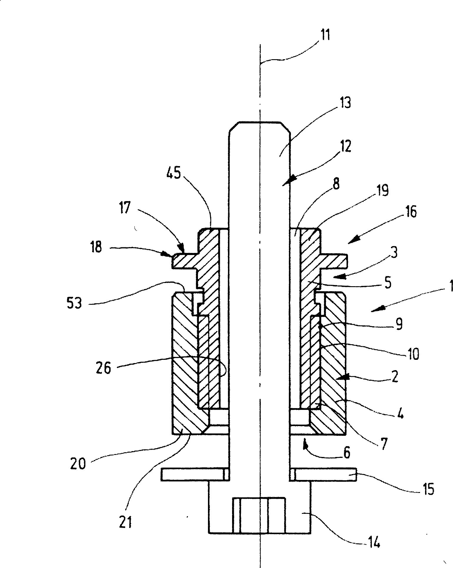
[0013] figure 1 A span device 1 is shown for mounting a roof strip on the roof of a vehicle. The span device 1 has a support part 2 and a counter support part 3 . The support part 2 is formed as an outer sleeve 4 and the counter-support part 3 is formed as an inner sleeve 5 . The outer sleeve 4 has an axial through hole 6 with an internal thread 7 . The inner sleeve 5 is equipped with an axial penetration groove 8 . An outer thread 10 is held on the outer surface 9 of the inner sleeve 5 . The inner thread 7 and the outer thread 10 are screwed together, ie the inner sleeve 5 is screwed axially into the outer sleeve 4 . Axial in figure 1 is marked with centerline 11.

[0014] From figure 1 It can be seen that a shaft section 13 with a thread 12 passes through the passage groove 8 and the corresponding part of the passage hole 6 . A washer 15 with a larger diameter is arranged at the head 14 of the thread 12 . From figure 1 It can be seen that the anti-support part 3 pr...


PUM


Abstract

The invention refers to a spacing device for bridging a gap between a carrier part and a roof body and intended for fastening a roof rack, roof rail, roof strip or the like on a vehicle roof, with a support part and a counter-support part, the support part and the counter-support part being held together by a screw connection and being displaceable relative to one another to allow the adjustment of the bridging length, the support part and / or counter-support part being provided with an internally disposed adjustment tool-gripping seat intended for the manipulation and / or adjustment of the bridging length.

Description

technical field [0001] The present invention relates to a span device for fastening roof racks, roof rails, roof slats or the like to the roof of a vehicle bridging the free space between the load carrying part and the top shell. Background technique [0002] Roof racks, roof rails, roof slats and the like are mounted on the roof of the car, and in this case they are not strongly supported on the sheet metal roof shell, but by a Span gear with load carrying parts to tie down. The load-carrying part is able to absorb the stresses that can occur under heavy roof loads, especially in the event of a breakdown (strong deceleration). The load carrier is not visible from the outside because it is located under the roof shell sheet metal. The load-carrying part is also not visible from the interior of the car because it is hidden by the inner lining of the body (roof lining). A free space is formed between the lower side of the roof shell and the upper side of the load-carrying p...

Claims


Application Information

Patent Timeline
Patent Type & Authority Patents(China)
IPC IPC(8): B60R9/04B62D65/16
CPCB60R9/04
Inventor 汉斯·宾德奥特马尔·宾德沃尔夫刚·沙贝尔
Owner SUDDEUTE ALUMINUM MANUFAKTUR
Features
  • R&D
  • Intellectual Property
  • Life Sciences
  • Materials
  • Tech Scout
  • Unparalleled Data Quality
  • Higher Quality Content
  • 60% Fewer Hallucinations
Learn More