Eureka AIR delivers breakthrough ideas for toughest innovation challenges, trusted by R&D personnel around the world.

Impactless vibration steel rail

A shock vibration and rail technology, applied in the joints of rails, tracks, roads, etc., can solve the problems of affecting passengers' rest and physical and mental health, increased shock vibration and noise, large shock vibration and noise, and achieves simple structure and reduced impact Effects of vibration and noise, shock-free vibration and noise

Inactive Publication Date: 2005-05-25
许宝庆 +1
View PDF0 Cites 2 Cited by
  • Summary
  • Abstract
  • Description
  • Claims
  • Application Information

AI Technical Summary

Problems solved by technology

When the fast-rotating wheel passes through the expansion joint between the rails, the wheel actually loses contact with the rail in an instant and jumps from one rail to the next. At this time, a large impact vibration and noise are generated. The impact, vibration and noise increased even more due to the speed-up operation. Although the long steel rail was used, the problem was not fundamentally solved. The impact, vibration and noise affected the rest and physical and mental health of passengers, and polluted the environment.

Method used


Image

  • Impactless vibration steel rail
  • Impactless vibration steel rail
  • Impactless vibration steel rail

Examples


Embodiment Construction

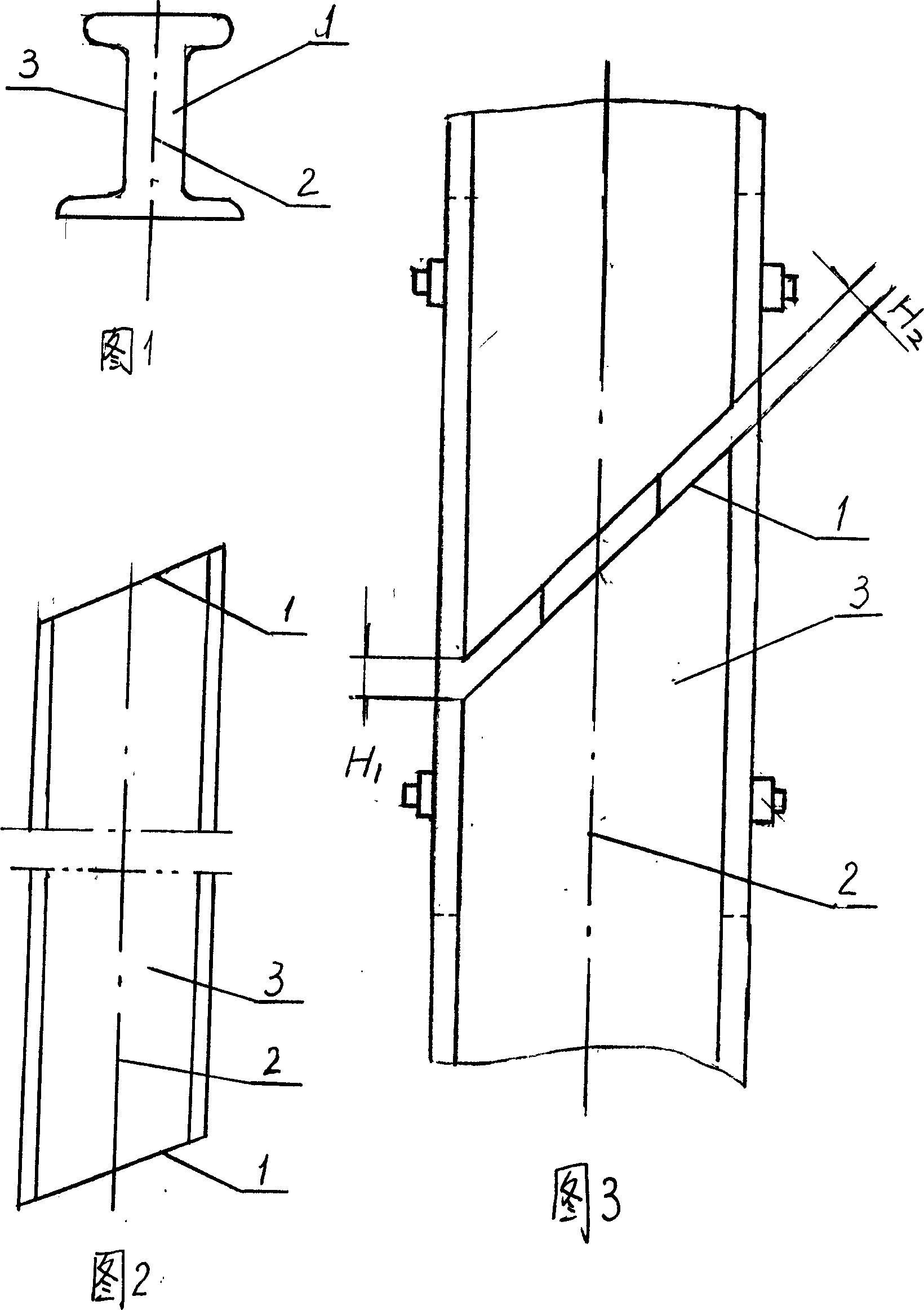
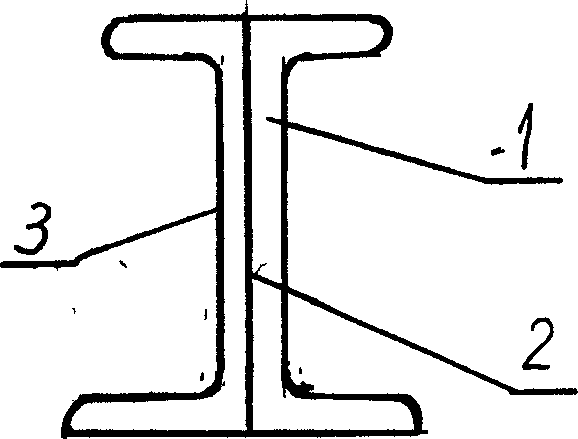
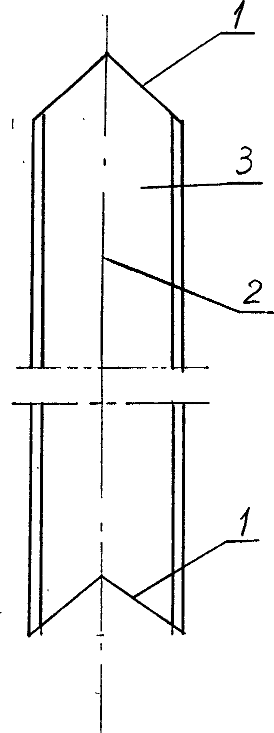
[0014] The best embodiment of the present invention will be described in detail below in conjunction with the accompanying drawings. A steel rail without shock and vibration, the end faces 1 of the two ends of the rail 3 are arranged in an inclined shape with respect to the longitudinal vertical surface 2 of the rail 3 in the horizontal direction, that is, the included angle is not equal to 90°, and the end faces 1 of the two ends are parallel to each other; or the rail The end faces 1 at both ends of 3 are respectively in the shape of a boss angle and a groove shape, and the size and angle of the boss angle end face and the groove angle end face are the same.

[0015] When the rail 3 is laid, the two ends of the rails with inclined end faces are connected, or the two ends of the rails with convex and concave angular end faces are matched, and the angular end faces of the convex platforms are located in the angular end faces of the grooves; the distance between the end faces is...


PUM


Abstract

The present invention relates to a steel rail free from impact vibration. It is characterized by that the end of faces of two ends of the rail and longitudinal vertical face of the rail are arranged according to the inclined form on the horizontal direction, namely its included angle is not equal to 90 deg, and the end faces of two ends are mutually parallel; or end faces of two ends of the rail are respectively made into the projected corner form and recessed corner form, and their size and angle are identical.

Description

technical field [0001] The invention belongs to a rail profile in rail traffic, and is mainly suitable for use in high-speed transportation vehicles such as trains and traffic facilities. Background technique [0002] At present, both ends of each railway rail are planar and form a vertical angle with the longitudinal vertical plane of the rail. In use, considering the physical phenomenon of thermal expansion and cold contraction, large expansion gaps are left at the joints of the connected rails, and the gaps increase in winter. When the fast-rotating wheel passes through the expansion joint between the rails, the wheel actually loses contact with the rail in an instant and jumps from one rail to the next. At this time, a large impact vibration and noise are generated. The speed-up operation, the impact vibration and noise are even more increased. Although the long steel rail is used, the problem has not been solved fundamentally. The impact vibration and noise affect the ...

Claims


Application Information

Patent Timeline
IPC IPC(8): E01B11/24
Inventor 许宝庆岳春生
Owner 许宝庆
Why Eureka
Eureka Blog
Learn More