Biimpact fast switching device

A fast switch and impact lever technology, applied in the direction of snap-action devices, electric switches, electrical components, etc., can solve the problems of loss of switch function, poor electrical contact quality of excitation point, damage of fixed contact head and movable contact head, etc., to achieve The effect of simple structure

Active Publication Date: 2005-05-25
ZHEJIANG CHINT ELECTRIC CO LTD
View PDF0 Cites 5 Cited by
  • Summary
  • Abstract
  • Description
  • Claims
  • Application Information

AI Technical Summary

Problems solved by technology

The consequence is that the electrical contact quality of the excitation point is particularly poor. When affected by environmental factors (such as vibration), the breaking current will be switched on and off at high frequency and irregularly, thus causing great damage to the fixed contact head and the movable contact head. Even lost the switch function

Method used


Image

  • Biimpact fast switching device
  • Biimpact fast switching device
  • Biimpact fast switching device

Examples


Embodiment Construction

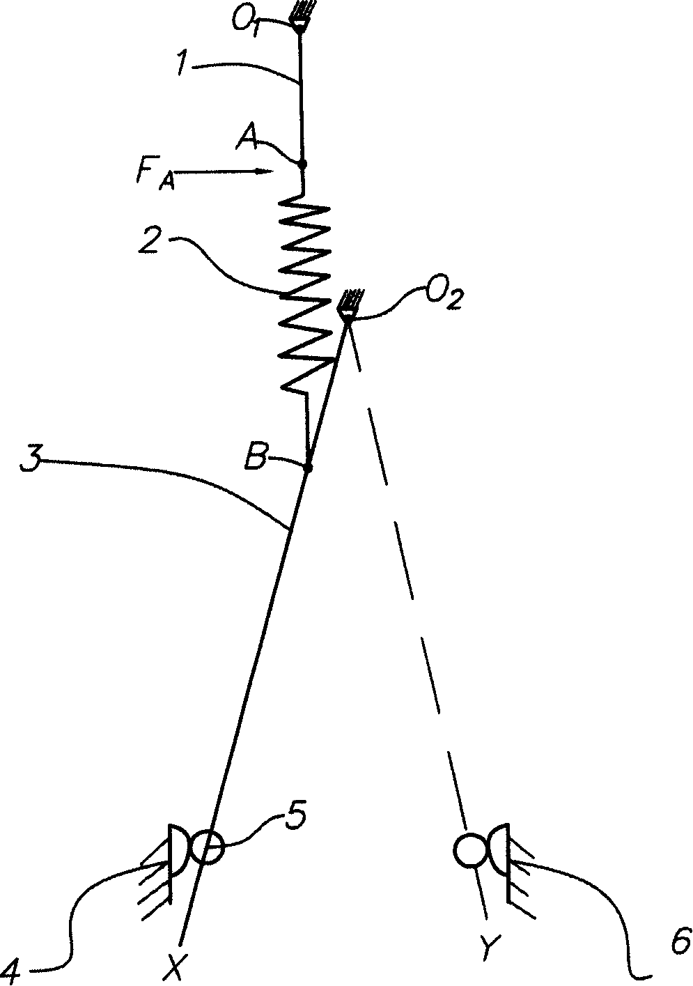
[0033] like figure 1 As shown, one end of the toggle lever 3 can be wound around the axis O 2 Rotate, and the other end is embedded in the double-sided contact moving contact 5. The toggle lever 3 can be wound around the axis O 2 It rotates between the two positions of X and Y, and its action is caused by the spring 2. One end B of the spring 2 is connected to the toggle rod 3, and the other end A is connected to the swing rod 1, and the swing rod 1 can be rotated around the axis O. 1 rotate. At the same time, the spring 2 also provides the contact pressure when the double-sided contact movable contact 5 is in contact with the movable and divided stationary contacts 4 or the movable and combined stationary contacts 6 . When one end A of spring 2 is subjected to force F A When acting, the spring 2 and the toggle lever 3 have associated actions, and when the toggle lever 3 rotates between the two positions of X and Y, it can only occupy one of the positions, so that the doub...


PUM


Abstract

A double percussion quick switch comprises knee level, swing link, spring, active on static contact, active off static contact, spring support piece for above contacts and percussion level. Said invention keeps the reliable switching on in active on static contact as passing the dead point and can push the knee level passing over the dead point quickly.

Description

technical field [0001] The invention relates to a switch for low-voltage electrical appliances, in particular to a double-impact quick switch device. Background technique [0002] Existing transfer switches include: [0003] - a toggle lever, one end is rotatably connected to the first fixed shaft, and the other end is provided with a double-sided contact movable contact; [0004] - a pendulum rod, one end of which is rotatably connected to the second fixed shaft; [0005] - a spring, the two ends of which are respectively connected to the other end of the pendulum rod and the toggle rod; [0006] - A moving-closing and static contact and a moving-dividing and static contact are respectively arranged opposite to the double-sided contact moving contacts. [0007] A horizontal force is applied at the connection between the swing rod and the spring, and the spring drives the toggle rod to rotate from the first steady state position to the second steady state position. [00...

Claims


Application Information

Patent Timeline
Patent Type & Authority Applications(China)
IPC IPC(8): H01H5/08
Inventor 李伟
Owner ZHEJIANG CHINT ELECTRIC CO LTD
Why Eureka
Try Eureka