Automatic calibration method for use in electronic compass

An electronic compass and azimuth technology, applied to compass, measuring device, surveying and navigation, etc., can solve the problem of not being able to update calibration data

Inactive Publication Date: 2005-06-08
SAMSUNG ELECTRO MECHANICS CO LTD
View PDF0 Cites 36 Cited by
  • Summary
  • Abstract
  • Description
  • Claims
  • Application Information

AI Technical Summary

Problems solved by technology

[0019] However, a drawback of the conventional calibration method determined above is that it requires a data input process by the user to perform a calibration process capable of calculating the offset and scale values ​​for the individual axes of the geomagnetic sensor
In addition, assuming that the surrounding environmental conditions change unexpectedly during the operation time of the electronic compass, the conventional calibration method described above cannot update the calibration data according to the changed surrounding environmental conditions.

Method used


Image

  • Automatic calibration method for use in electronic compass
  • Automatic calibration method for use in electronic compass
  • Automatic calibration method for use in electronic compass

Examples


Embodiment Construction

[0036] Now, preferred embodiments of the present invention will be described in detail with reference to the accompanying drawings. In the drawings, the same or similar elements are denoted by the same reference numerals even if they are depicted in different drawings.

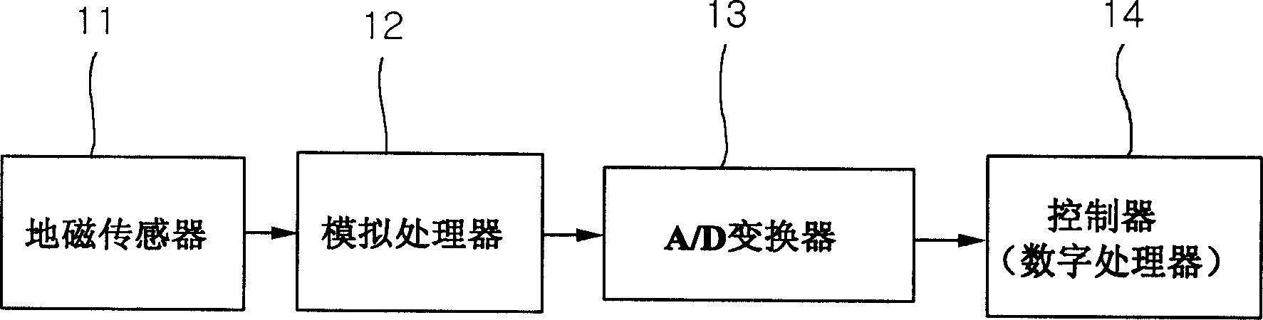
[0037] Figure 4 is a block diagram illustrating the control module of the electronic compass of the present invention.

[0038] see Figure 4, the minimum and maximum calibration valid times T1 and T2 required by the system containing the controller are predetermined by the control module within the electronic compass. The minimum calibration valid time T1 is the minimum time during which the calibration data can be considered valid, and the maximum calibration valid time T2 is the maximum time during which the calibration data can be considered valid. In order to perform a valid calibration operation, the calibration duration must be longer than the minimum calibration valid time T1 and shorter than the m...


PUM


Abstract

An automatic calibration method used in an electronic compass. Using this automatic calibration method, the electronic compass automatically calculates and corrects the offset and scale values ​​of the geomagnetic signal by detecting one rotation of the geomagnetic axis during a predetermined period. The electronic compass calculates the azimuth when it receives the geomagnetic data from the geomagnetic sensor and uses the received geomagnetic data to find the maximum and minimum values ​​of the sensor signals of the individual axes of the geomagnetic sensor so that it can correct or calibrate the deviation of the azimuth . When the time taken for calibration is equal to or shorter than the maximum calibration valid time, the electronic compass determines whether the current state of the detected input signal indicates a predetermined steady state flow. If the current state represents a steady state flow, while a signal representing one revolution of the geomagnetic sensor is received, and the calibration takes longer than the predetermined minimum calibration valid time, the electronic compass uses the maximum and minimum values ​​to calculate the offset and scale values ​​and store the calculated offset and scale values.

Description

technical field [0001] The present invention relates to an automatic calibration method for use in an electronic compass, and more particularly to an automatic calculation and correction of an offset of a geomagnetic signal for use in an electronic compass by detecting one rotation of the geomagnetic axis during a predetermined period using a timer and scale values, performing automatic calibration capable of calculating the offset and scale values ​​of the geomagnetic signal without receiving additional input data from the user, and an automatic calibration method that quickly responds to environmental changes. Background technique [0002] Recently, small and low-priced geomagnetic sensor modules and electronic compasses have been developed. With the increasing development of MEMS (Micro Electro Mechanical System) technology, chip-sized geomagnetic sensor modules have been newly developed and used for various applications. There is a need for a geomagnetic sensor that con...

Claims


Application Information

Patent Timeline
Patent Type & Authority Applications(China)
IPC IPC(8): G01C17/32G01C17/38
CPCG01C17/38
Inventor 姜镇龙崔愿太金畅炫郑夏雄赵汉喆权五照
Owner SAMSUNG ELECTRO MECHANICS CO LTD
Why Eureka
Try Eureka