Method of extracting raster line in structural optical through colour coding and comparative method

A technology for color coding and structure extraction, applied in the computer field, which can solve the problem of low robustness

Inactive Publication Date: 2005-06-08
INST OF AUTOMATION CHINESE ACAD OF SCI
View PDF0 Cites 1 Cited by
  • Summary
  • Abstract
  • Description
  • Claims
  • Application Information

AI Technical Summary

Benefits of technology

This technology allows an object's colors or patterns on both sides of its line to change slightly when viewed from one side towards another without affecting how it looks like they were before being captured with regular projection equipment such as LCD displays (Liquid Crystal Display). It does this through special techniques that remove false gratings caused during normal viewing conditions but still allow us to capture detailed details about these scenes quickly enough at all times.

Problems solved by technology

Technological Problem: Current methodologies for reconstructing objects by combining multiple layers with varying levels of detail (LOD), such as adding shading effects during photography). However, there exist challenges related to accurate detection and identification of specific features within each layer's boundaries that help improve the quality of these models. Additionally, current techniques involve capturing data through an unnatural environment where noise interference occurs frequently due to factors like uneven illumination caused by external sources or background clutter.

Method used


Image

  • Method of extracting raster line in structural optical through colour coding and comparative method
  • Method of extracting raster line in structural optical through colour coding and comparative method
  • Method of extracting raster line in structural optical through colour coding and comparative method

Examples


Embodiment Construction

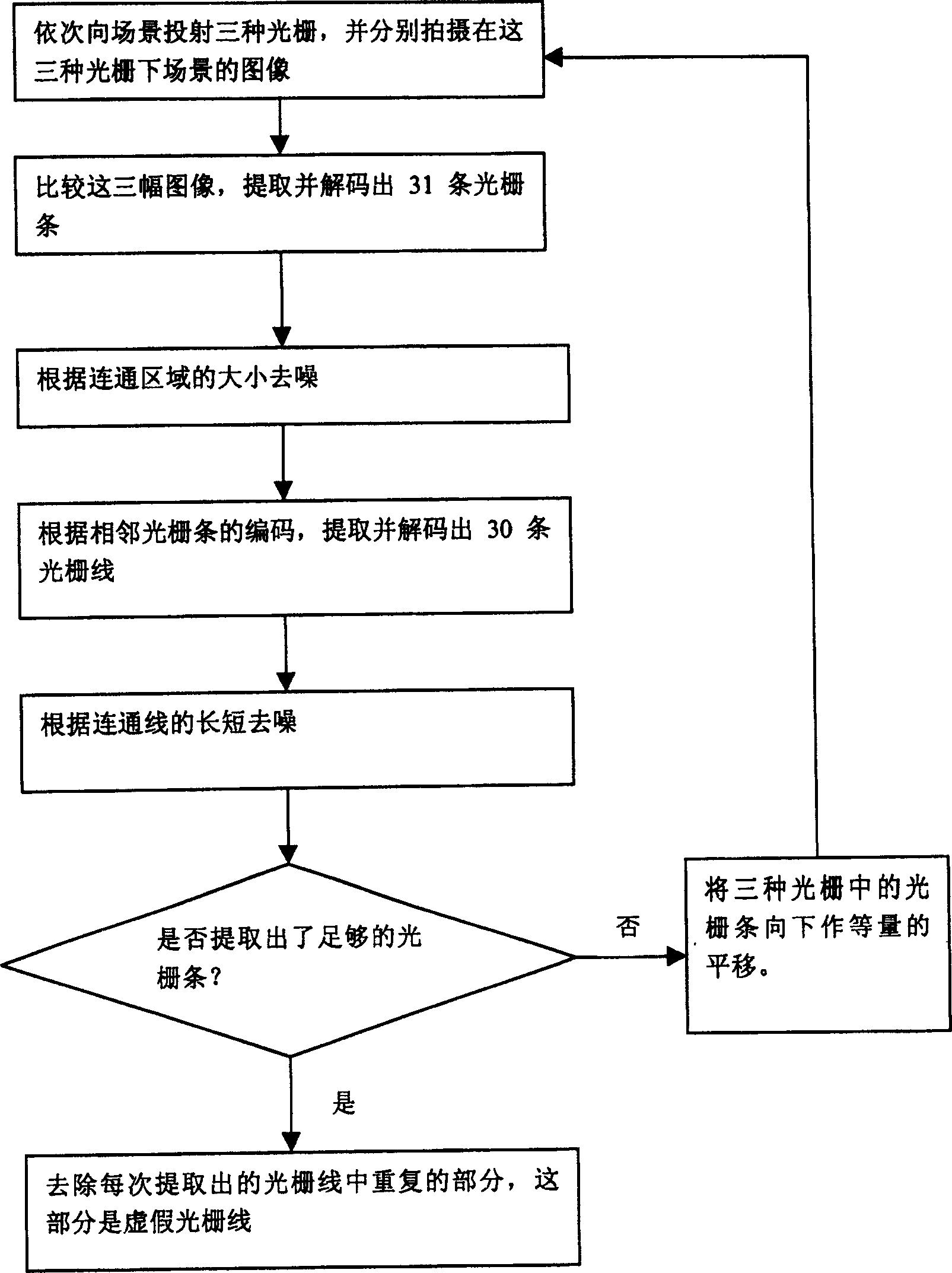
[0030] The inventive method requires a projector, a computer and a video camera controlled by the computer. The position of the camera is fixed during raster projection and filming. The method is described in detail in 5 parts:

[0031] 1. Raster encoding.

[0032] This method projects three kinds of gratings sequentially each time, such as figure 2 As shown, compare the three images taken to extract 30 raster lines. Each grating consists of 31 horizontal grating bars. The color of each grating bar is one of red, green and blue. Raster strip width W ≈ Height 31 , Where Height is the height of the computer display. The 31 grating bars are recorded as the first, second, ..., 31st grating bars in sequence from top to bottom. The positions and widths of the same numbered grating bars are the same in each type of grating, only the color is different. According to the three different color changes, ...


PUM


Abstract

The invention relates to a computer technology, and is a method to pick up the raster line of the structure light using color code and comparative method. The processes are: a) projecting color raster of three codes to the scene orderly, and respectively shooting picture of the scene irradiated by the three raster; b) comparing the size of the color heft of every corresponding pels points of the three pictures, pick up and encode each raster bar; c) according to the number of the pels containing in the pels bar, eliminating the noise point; d) according to the adjacent relation of the pels bar, picking up and encoding the raster lines; e) according to the length of the connective raster lines, eliminating the noise point; f) moving paralleled downward the raster bars of the three kinds of raster with equal distance; g) according to the new picture shot extract and encoding the new raster lines; h) comparing the raster lines and eliminating the repeated parts; j) if need to pick up more raster lines, and repeating the processes.

Description


Claims


Application Information

Patent Timeline
Owner INST OF AUTOMATION CHINESE ACAD OF SCI
Why Eureka
Try Eureka