
Solder wire container

A welding wire and container technology, applied in the field of welding wire, can solve problems such as easy tilting

Active Publication Date: 2005-06-15
KOBE STEEL LTD
View PDF5 Cites 20 Cited by
  • Summary
  • Abstract
  • Description
  • Claims
  • Application Information

AI Technical Summary

Problems solved by technology

Therefore, there arises such a problem that the holding plate 120 is easily tilted, and the welding wire is easily entangled with each other to become tangled.

Method used


Image

  • Solder wire container
  • Solder wire container
  • Solder wire container

Examples


Embodiment Construction

[0058] (first aspect of the present invention)

[0059] Now, a welding wire container according to an embodiment of the first aspect of the present invention will be described in detail with reference to the accompanying drawings.

[0060] (basic structure of welding wire container)

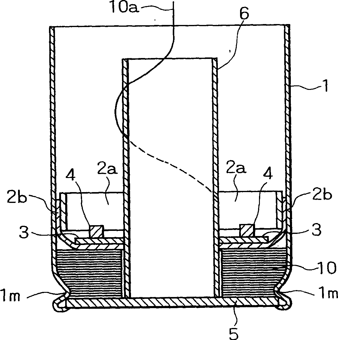
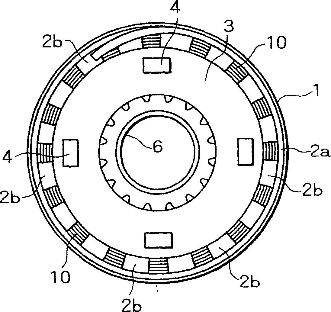
[0061] Figure 1A is a cross-sectional view of a welding wire container according to an embodiment of the first aspect of the invention, Figure 1B is its floor plan. In the welding wire container according to this embodiment, the portion slightly higher than the lower end portion of the circular outer cylinder 1 is indented. A bottom plate 5 forming the bottom of the container is mounted to the lower portion closest to the indented portion so as to be held inside the outer cylinder 1 . The bottom plate 5 is fixed to the outer cylinder 1 by a metal reinforcement plate surrounding the indented portion of the outer cylinder 1 and the bottom surface of the bottom plate 5, as described below. Us...


PUM


Abstract

A welding wire container for holding a coil of welding wire, comprising: an outer cylinder of paper; a base plate held by the interior of the outer cylinder at an indented portion of the lower portion of the outer cylinder, the base plate forming the bottom portion; A cage that moves downward as the filler wire decreases; and a ring member mounted on the cage whose outer diameter is smaller than the minimum inner diameter of the outer cylinder. The cage includes a diameter-adjustable tubular portion formed by rolling up a belt member, and a plurality of blade portions extending from an inner edge of a lower portion of the tubular portion toward the center of the tubular portion. The loop member acts as a plumb for the cage as the wire is pulled out of the container. With the above structure, the welding wire can be smoothly deployed to the bottom layer of the welding wire without being entangled with each other.

Description

technical field [0001] The present invention relates to welding wire containers for containing coils of welding wire therein and to welding wire in the containers. In particular, the invention relates to such a welding wire container which is suitable for rigid solid welding wire. Background technique [0002] As a container for accommodating welding wire such as solid wire or flux-cored wire, a wire container with a cylindrical bottom is generally used (for example, refer to JP59-8474B and JP3-34424B). Figure 34 is a schematic perspective view of a conventional welding wire container. Figure 35 Yes Figure 34 A cross-sectional view of the wire container shown in, Figure 36 It is a perspective view only showing a holding board. like Figure 34 and 35 As shown, the welding wire in the conventional container is wound and contained in the container in such a manner that the welding wire 100a moves its central axis along a circular trajectory. The container has a bottom p...

Claims


Application Information

Patent Timeline
IPC IPC(8): B65D85/26B23K9/133B65D85/04B65D85/67B65H75/16
CPCB23K9/133B65D85/04B65D85/26B65D85/67B65H54/76B65H59/06
Inventor 小松伸二宫崎邦彰清水弘之北野正治政家规生
Owner KOBE STEEL LTD
Learn More