
Equipment at a lift cage for temporarily coupling a cage door leaf with a shaft door leaf and for actuation of a cage door unlocking means

一种轿厢门扇、耦合件的技术,应用在轿厢门扇与竖井门扇耦合和对轿厢门去闩锁件促动的装置领域,能够解决增大弯曲应力、增大弹簧断裂的风险等问题,达到低摩擦损耗的效果

Inactive Publication Date: 2005-06-15
INVENTIO AG
View PDF1 Cites 13 Cited by
  • Summary
  • Abstract
  • Description
  • Claims
  • Application Information

AI Technical Summary

Problems solved by technology

Also a larger travel path will increase the bending stress on the guide spring and thus increase the risk of spring breakage

Method used


Image

  • Equipment at a lift cage for temporarily coupling a cage door leaf with a shaft door leaf and for actuation of a cage door unlocking means
  • Equipment at a lift cage for temporarily coupling a cage door leaf with a shaft door leaf and for actuation of a cage door unlocking means
  • Equipment at a lift cage for temporarily coupling a cage door leaf with a shaft door leaf and for actuation of a cage door unlocking means

Examples


Embodiment Construction

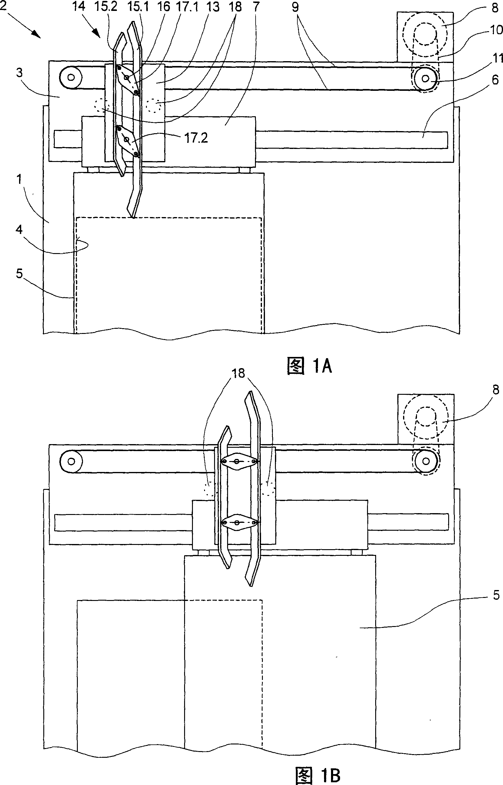
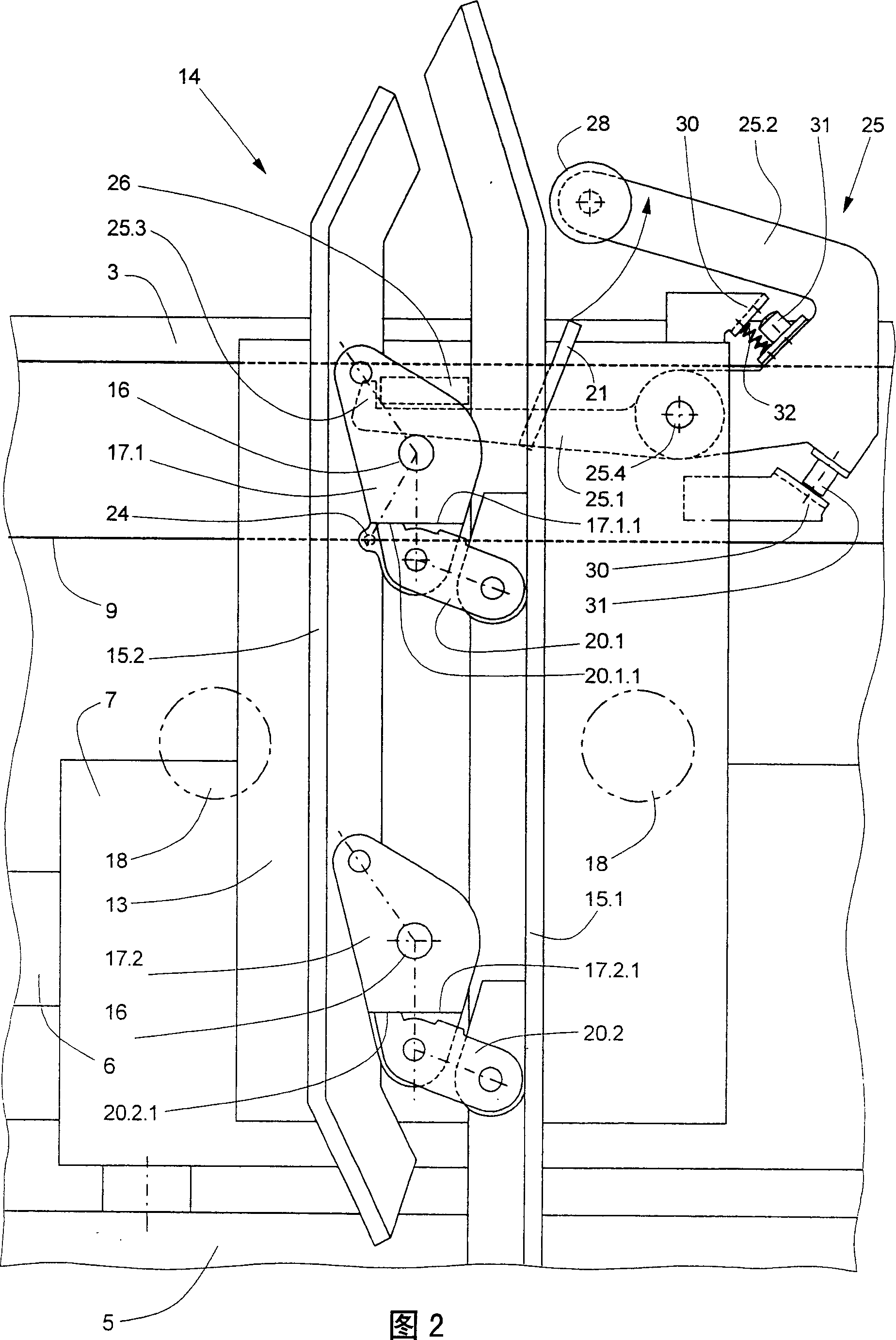
[0029]Figures 1A and 1B schematically show an electric door drive device 2, which is installed on an elevator car 1 for lateral closing of a single door. In the figure, an elevator car 1 with a door opening 4 that can be closed by a car door leaf 5 is shown. The elevator door driving device 2 is installed on a door bracket 3 which is fixed on the elevator car 1. The door leaf 5 is fixed on the hanging door sliding seat 7, and the hanging door sliding seat 7 can move laterally along a guide rail 6 fixed on the door bracket, and the hanging door sliding seat is driven by a linear action reciprocating drive through the drive unit 8. The device moves between the open position of the door leaf and the closed position of the door leaf. The motor drives the driving wheel 11 of the linearly acting driving member 9 through the transmission member 10 at an adjusted or unadjusted rotation speed, and functions as the driving unit 8. The linearly acting drive member 9 can be a toothed belt, a ...


PUM


Abstract

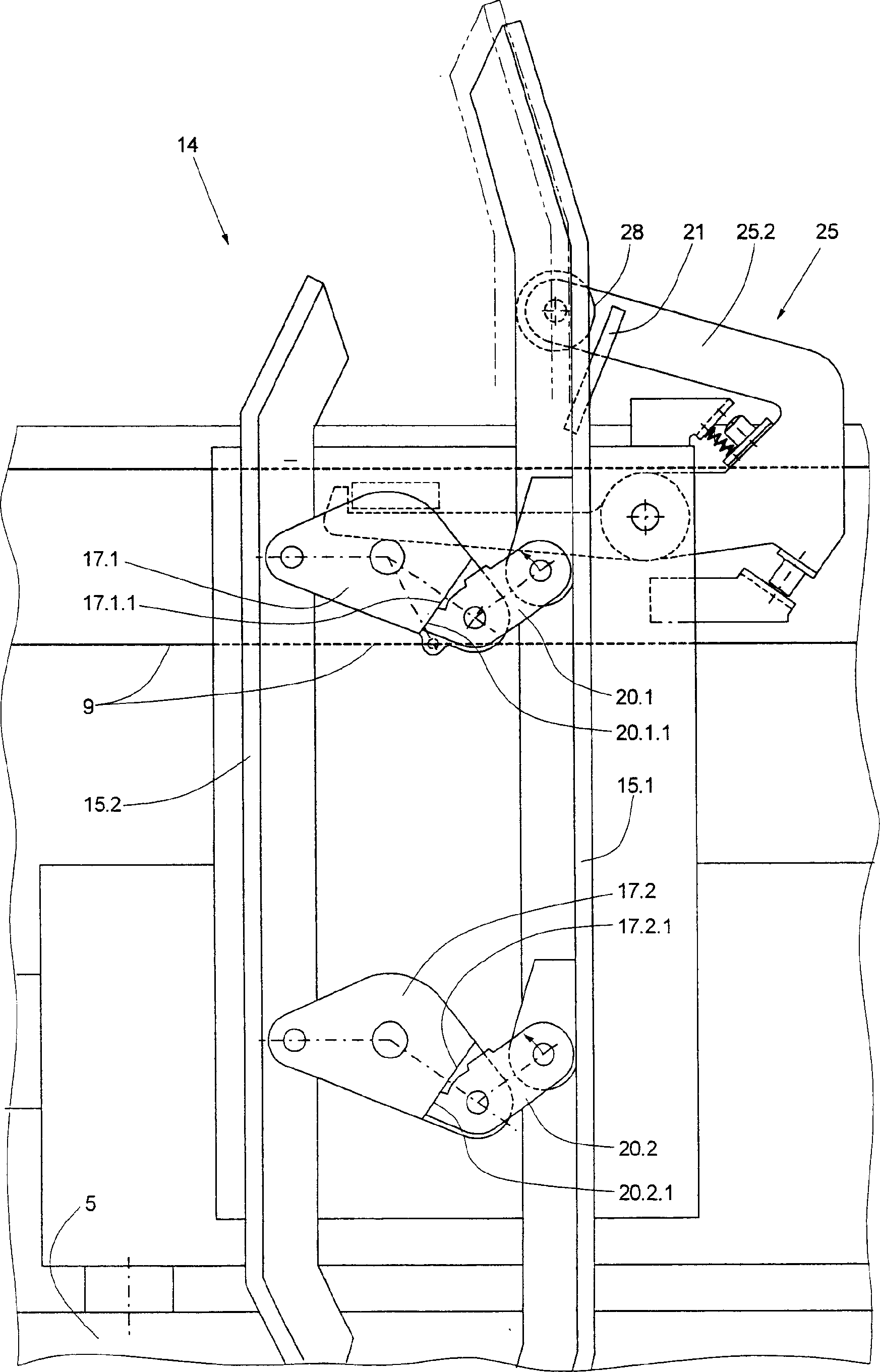
The device on a lift car for the temporary coupling of a lift car door wing (5) to a shaft door wing and for the operating of a car door lock (25) has two drive runners (15.1,15.2) connected to adjusting elements (17.1,17.2). One runner is connected by a respective articulated component (20.1, 20.2) to one arm of each adjusting element, and as a result of the contact force (F) from the shaft door wing coupling element (18) acting on the drive runner the drive runner executes an accurately guided additional movement which effects the unlocking of the lift car door lock.

Description

Technical field [0001] The invention relates to a device for temporarily coupling a car door leaf and a shaft door leaf and activating a de-latching member of the car door. Background technique [0002] The problem involved in the present invention is that only when the elevator car is located at the height of the floor, that is, when the car door is aligned with the shaft door, the elevator car door leaf is allowed to open and move. [0003] EP0332841 discloses a door drive device with a coupling mechanism, which is used to couple the car door leaf and the matching shaft door leaf. The coupling mechanism has two skid members, the skid members are parallel to each other in the running direction of the elevator car and the mutual spacing is adjusted by using a parallelogram guide with two adjustment members, and each adjustment member can surround its corresponding The swing axis swings. When the elevator car is exactly at the height of one floor, the two sliding parts are between...

Claims


Application Information

Patent Timeline
Patent Type & Authority Applications(China)
IPC IPC(8): B66B13/12B66B13/06B66B13/16B66B13/18
CPCB66B13/12
Inventor 丹尼尔·比桑于尔根·吕托尔夫弗兰克·蒂洛夫
Owner INVENTIO AG
Learn More