Helicopter without rotors

A technology of rotors and fins, applied in the field of active vertical lift vehicles, which can solve the problems of large energy loss, short helicopter range, and low quality factor of rotors

Inactive Publication Date: 2005-06-22
TANGSHAN DA TANG POWER MACHINERY
View PDF0 Cites 3 Cited by
  • Summary
  • Abstract
  • Description
  • Claims
  • Application Information

AI Technical Summary

Problems solved by technology

[0002] Disadvantages of modern helicopters: (1) During cruising, the rotor tilts forward to provide both lift and forward pulling force. Because the quality factor of the rotor is too lo

Method used


Image

  • Helicopter without rotors
  • Helicopter without rotors

Examples


Embodiment Construction

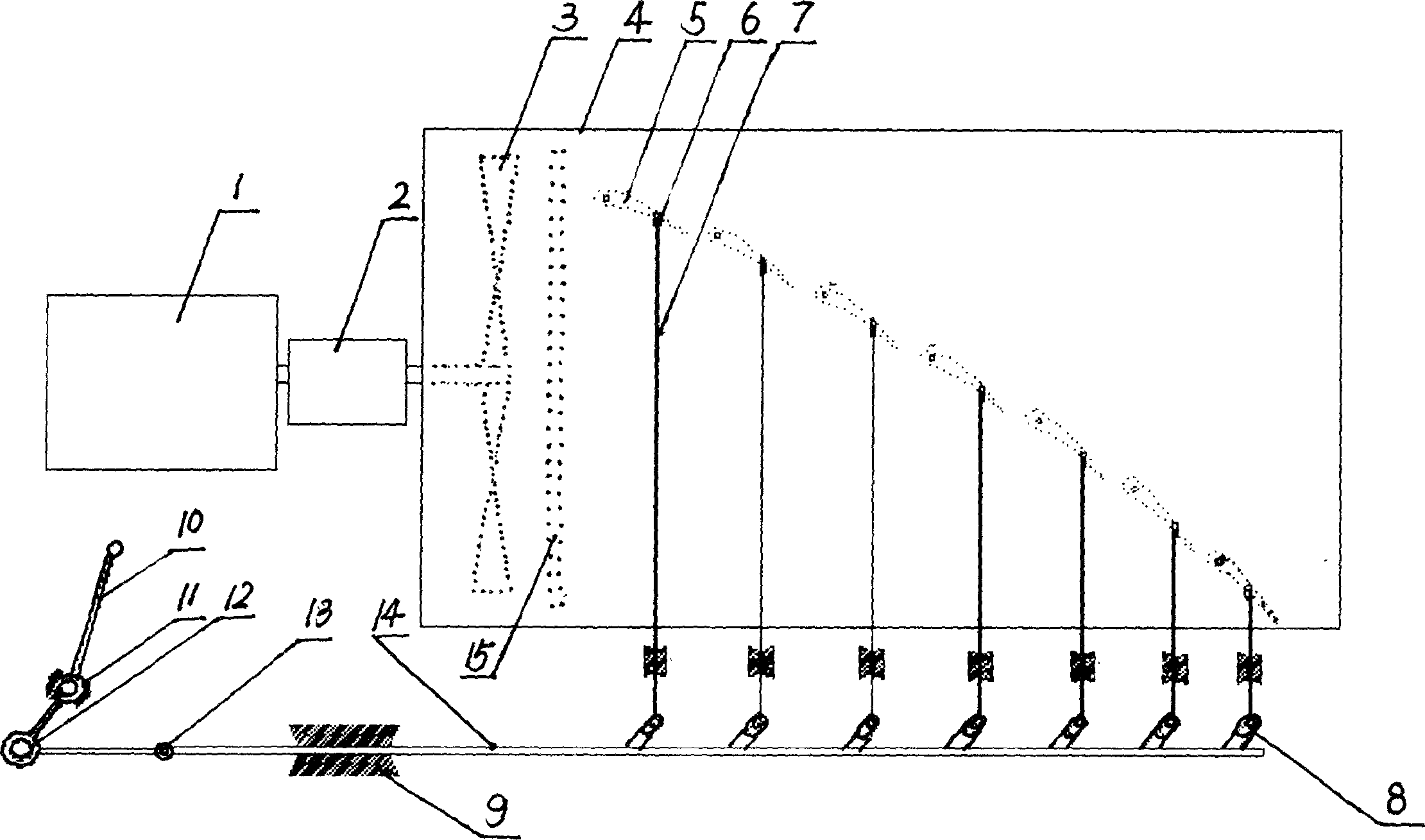
[0007] A specific embodiment of the present invention is given below in conjunction with the accompanying drawings. The non-rotor vertical lift-off device described in this embodiment consists of engine 1, gearbox 2, fan 3, windshield 4, wing 5, connecting rod shaft knot 6, attitude adjusting connecting rod 7, connecting rod hook 8, slide Rail 9, handle 10, fixed shaft wheel 11, attitude adjustment slipknot 12, alignment slipknot 13, movable connecting rod 14, rectifying grid mechanism 15 are formed, engine 1---be behind gearbox 2 with left and right ends windshield 4 (figure The left panel is shown in the middle, and the right panel is omitted) to form a semi-wind tunnel structure. The fan 3 is accommodated in the semi-wind tunnel structure. The airflow direction blown out by the fan 3 is provided with a gusset wing group mechanism composed of fins 5. Each wing The blades 5 are movably installed on the windshields 4 at the left and right ends through their end shafts. The bla...


PUM


Abstract

This invention relates to a drive vertical aircraft technique field and especially to a device without rotary blades, which comprises motor, gearbox and fan and also left and right block plates of the semi-fan hole. The gas flow from the fan is located with blade group structure composed of blades, wherein each blade is located on the left and right block plate through its end axis and is distributed from high to low and the blade group is located with blade facing angel adjusting structure.

Description

Technical field: [0001] The invention relates to the technical field of active vertical lift-off aircraft, in particular to a rotorless vertical lift-off device. Background technique: [0002] Disadvantages of modern helicopters: (1) During cruising, the rotor tilts forward to provide both lift and forward pulling force. Because the quality factor of the rotor is too low, the energy loss is too large, so the range of the helicopter is too short, which leads to , the desert, and the grasslands are unable to perform tasks, let alone fly across the ocean. (2) The rotor is flying naked and violently, and cannot walk through complex ground features to perform rescue, fire fighting and arrest. Invention content: [0003] The purpose of the present invention is to provide a vertical lift and overcome the disadvantages (2) in the background technology, with a high C L : C D The dead wing provides the lift in cruising, overcomes the drawback (2) described in the background techn...

Claims


Application Information

Patent Timeline
IPC IPC(8): B64C29/00
CPCB64C29/0025
Inventor 李治国
Owner TANGSHAN DA TANG POWER MACHINERY
Why Eureka
Try Eureka