
Decorative component, method of manufacturing a decorative component, timepiece, and decorated component

A technology for decorative parts and manufacturing methods, which is applied in clocks, clocks, mechanically driven clocks, etc., can solve the problems of monotonous appearance color and cannot correspond to diversified designs, and achieves promotion of design diversification, improved visibility, and setting The effect of increased degrees of freedom

Inactive Publication Date: 2005-06-22
SEIKO EPSON CORP
View PDF1 Cites 8 Cited by
  • Summary
  • Abstract
  • Description
  • Claims
  • Application Information

AI Technical Summary

Problems solved by technology

However, in conventional decorative parts manufactured by electroforming, the appearance is flat or the color is monotonous, and it may not be able to cope with various designs.

Method used


Image

  • Decorative component, method of manufacturing a decorative component, timepiece, and decorated component
  • Decorative component, method of manufacturing a decorative component, timepiece, and decorated component
  • Decorative component, method of manufacturing a decorative component, timepiece, and decorated component

Examples


no. 1 approach

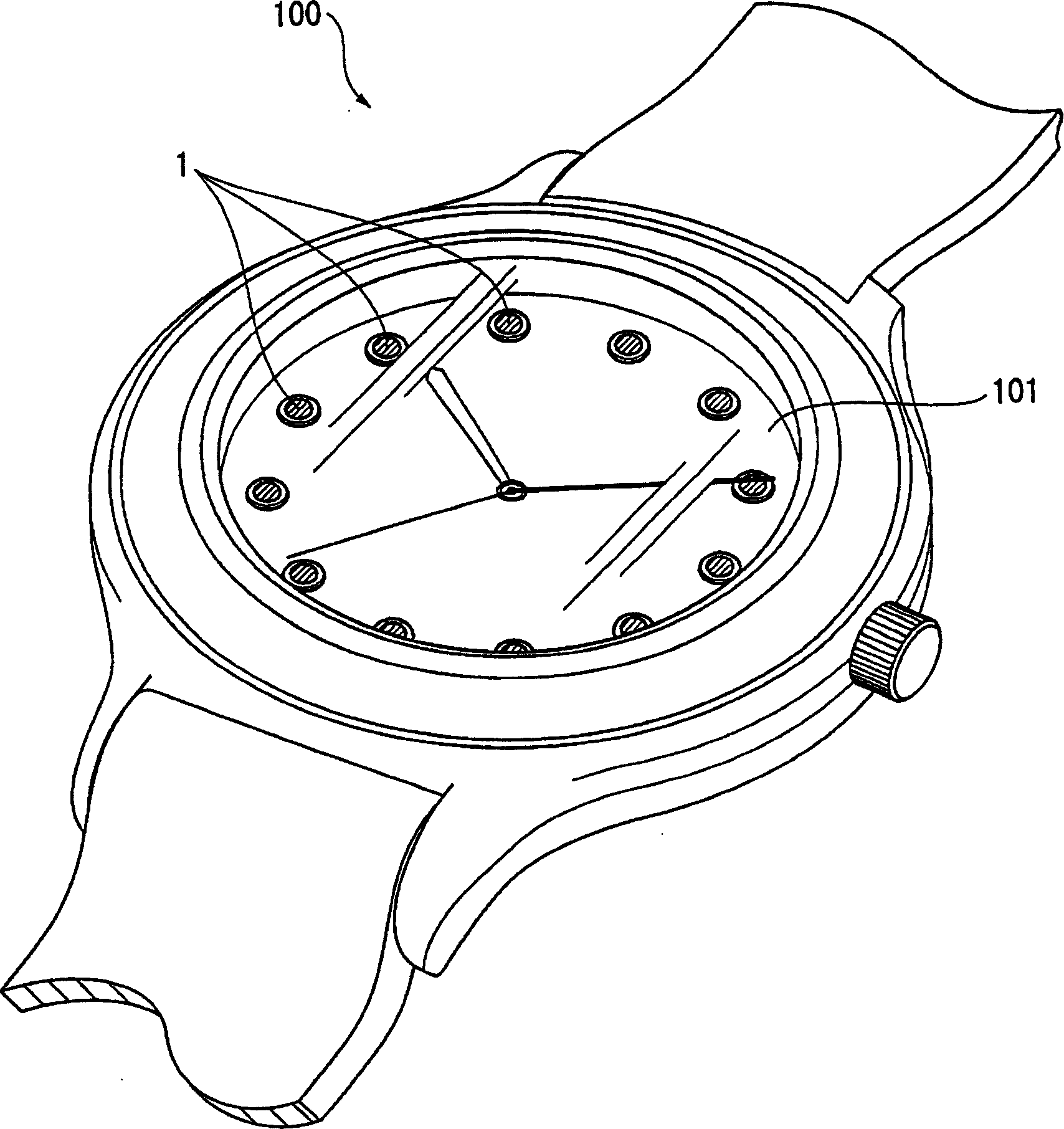
[0079] figure 1 A timepiece 100 using the scale member 1 as the decorative member according to the first embodiment of the present invention is shown. in the figure 1 Among them, the scale member 1 is pasted on a dial (base member) 101 of a watch 100 as a member to be decorated for decorating the clock 100 , and a plurality of scale portions are bonded to the dial 101 .

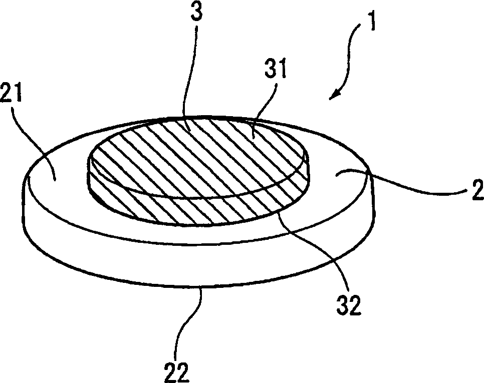
[0080] figure 2 A perspective view of the scale member 1 is shown. in the figure 2 Among them, the scale component 1 has: the first electroformed part 2 as the electroformed part pasted on the dial 101; and the second electroformed part as the decorative part formed on the decorative surface 21 of the first electroformed part 2 3.

[0081] The first electroformed part 2 is made by electroforming, and has an adhesive surface 22 that is attached to the dial 101 with an adhesive or the like; except for the adhesive surface 22 , the decorative surface 21 can be seen from the outside. The first electroform...

no. 2 approach

[0130] Next, a second embodiment of the present invention will be described. The structure of the decorative portion of the second embodiment is different from that of the first embodiment.

[0131] Figure 12 A perspective view showing a scale member 1A as a decorative member according to the second embodiment of the present invention. Such as Figure 12 As shown, the scale member 1A has: an electroformed part 2A pasted on the dial 101; and an electrodeposition sprayed part 3A as a surface treatment part (decorated part) formed on the decorative surface 21A of the electroformed part 2A.

[0132] The electroformed part 2A is formed in the same shape as the first electroformed part 2 of the first embodiment.

[0133] The electrodeposition sprayed part 3A is formed on the electroformed part 2A by electrodeposition spraying, and has: a fixed surface 32A fixed on the decorative surface 21A of the electroformed part 2A; Decorative surface 31A. The electrodeposition spraying pa...


PUM


Abstract

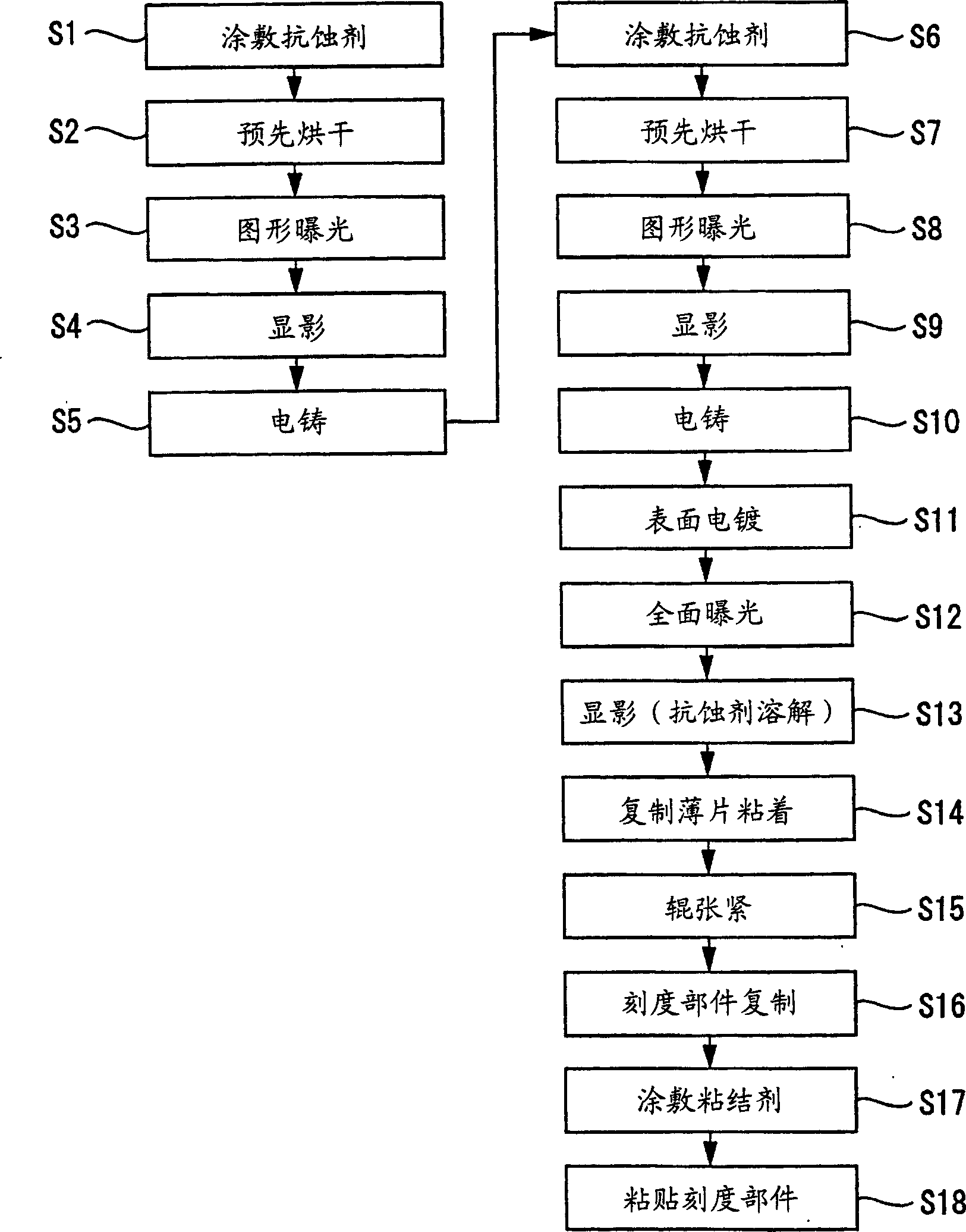
The invention relates to providing a decorative component that can be adapted to a large variety of designs, to provide a method for manufacturing the decorative component, and to provide a decorated component or a timepiece provided with the decorative component manufactured by the method for manufacturing the decorative component. A first resist is formed on a substrate 4, and a first electroformed part 2 is formed. A second resist is then formed on the decorative face 21 of the first electroformed part 2, and a second electroformed part 3 is formed. A plating is applied as a surface treatment on the decorative face 31 of the second electroformed part 3, the first resist and second resist are then removed, and an indicator component 1 is manufactured. The second electroformed part 3 is formed directly on the decorative face 21 of the first electroformed part 2, so a multi-stage electroformed part can be formed, a more pronounced three-dimensional look can be produced, and a greater variety of designs can be obtained. <IMAGE>

Description

technical field [0001] The present invention relates to a decorative part formed by electroforming, a method for manufacturing the decorative part, a timepiece with the decorative part, and a decorated part with the decorative part. Background technique [0002] Decorative parts such as letters, numerals, and patterns that are pasted on dials of watches and the like are produced by electroforming (for example, Patent Document 1). Since the decorative part produced by electroforming has a certain thickness, it is possible to produce a three-dimensional decorative part. In addition, since the decorative part can be made of metal, it can appear high-end. [0003] Patent Document 1 Japanese Patent Application Laid-Open No. 10-25591 (pages 3 to 5) [0004] However, with the diversification of designs of decorative objects such as clocks and watches in recent years, further three-dimensional effects and design diversification of decorative parts have been demanded. However, in ...

Claims


Application Information

Patent Timeline
Patent Type & Authority Applications(China)
IPC IPC(8): G04B19/06A44C27/00C23C28/00C25D1/00G04B19/12G04D3/00
CPCG04B19/12G04D3/0092
Inventor 森元邦明
Owner SEIKO EPSON CORP
Learn More