Anti-knock container

A container and outer cylinder technology, applied in the field of anti-explosion containers, can solve the problems of difficult gas discharge, small capacity of anti-explosion containers, thread wear, etc., to reduce shock wave overpressure and noise, improve anti-explosion and explosion-proof performance, anti-explosion Good explosion-proof performance

Active Publication Date: 2005-06-29
蒋友明
View PDF0 Cites 51 Cited by
  • Summary
  • Abstract
  • Description
  • Claims
  • Application Information

AI Technical Summary

Problems solved by technology

[0003] Existing anti-explosion containers are generally composed of a container body and an upper cover. The upper cover and the container main body are usually connected by threads or flanges. These anti-explosion containers generally have a small capacity, and their loading capacity is difficult to meet market demand.
Due to the poor thread strength of the threaded container, frequent opening and closing will cause serious thread wear and affect the service life of the anti-explosion container; and the lower part of these containers must be equipped with an explosion-proof diaphragm. When the explosion-starting equipment in the container explodes, The explosion-proof diaphragm is washed away first, and the detonation gas generated by the explosion is immediately discharged from the lower part of the container, and the harmful gas generated by the explosion cannot be discharged to a suitable place, polluting the environment; if this container is installed on a car, its discharge The mouth is aimed at the fuel tank at the lower part of the car, or the spare tire, the beam, etc., and there are many unsafe factors; The shock wave overpressure and noise generated by the gas have greatly exceeded the prescribed standards, and will have adverse effects on pedestrians near the explosion point.
Although the anti-explosion container with flange connection has good safety performance during use, it is very inconvenient to open and close. less practical

Method used


Image

  • Anti-knock container
  • Anti-knock container
  • Anti-knock container

Examples


Embodiment Construction

[0015] The present invention will be further described below with reference to the accompanying drawings and examples.

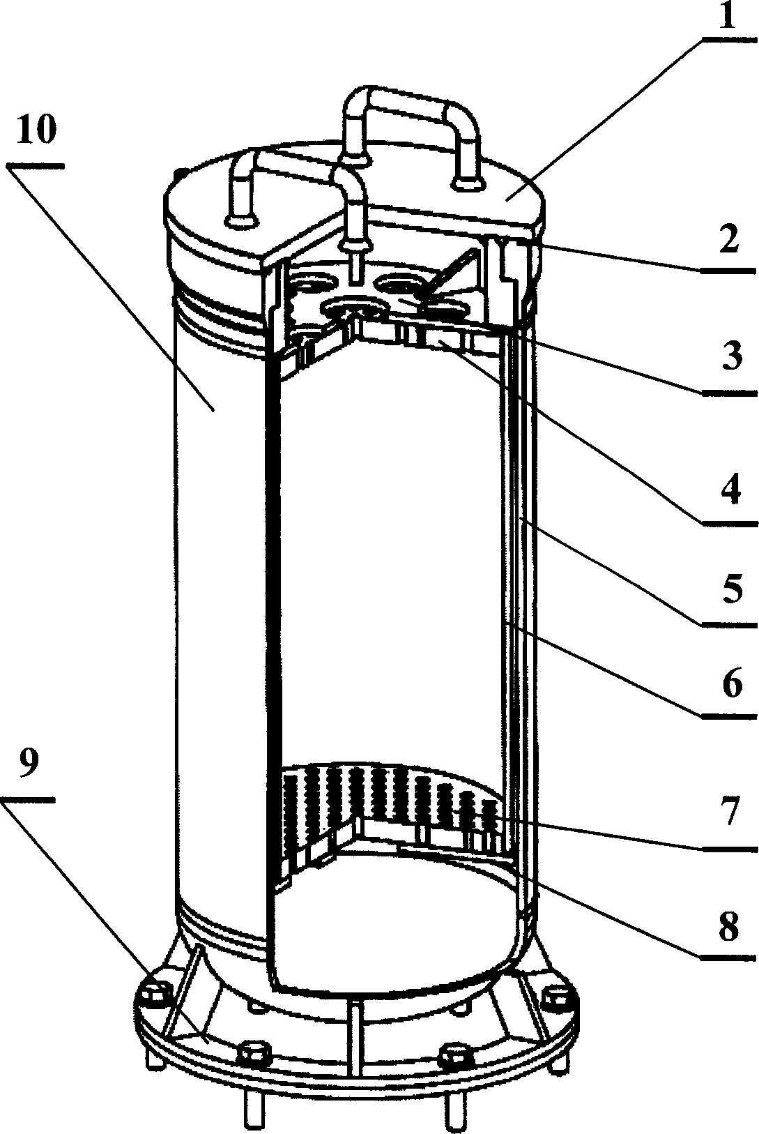
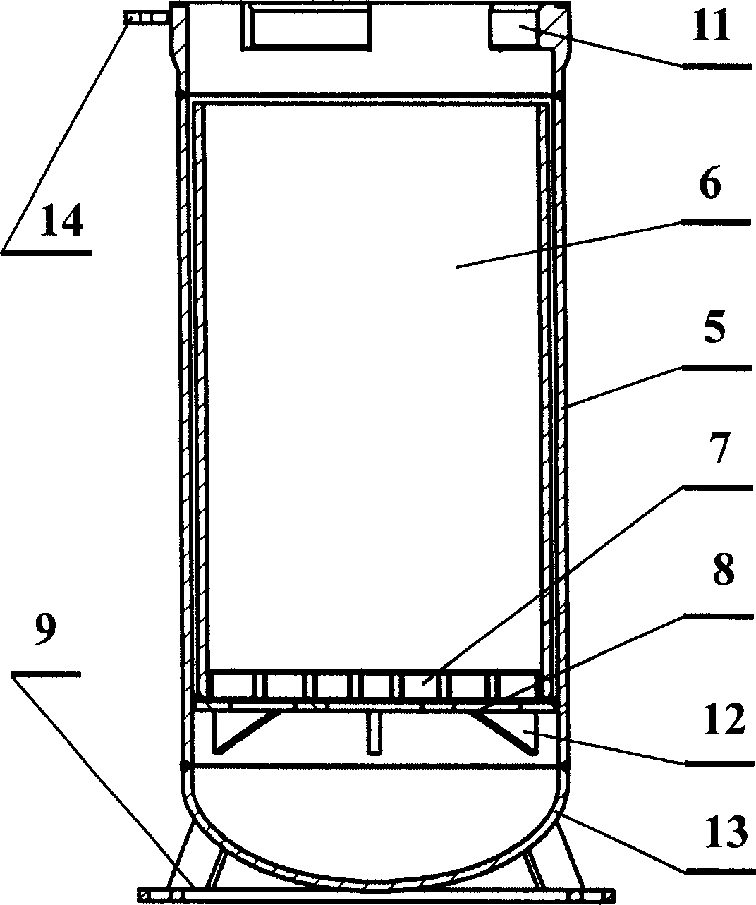
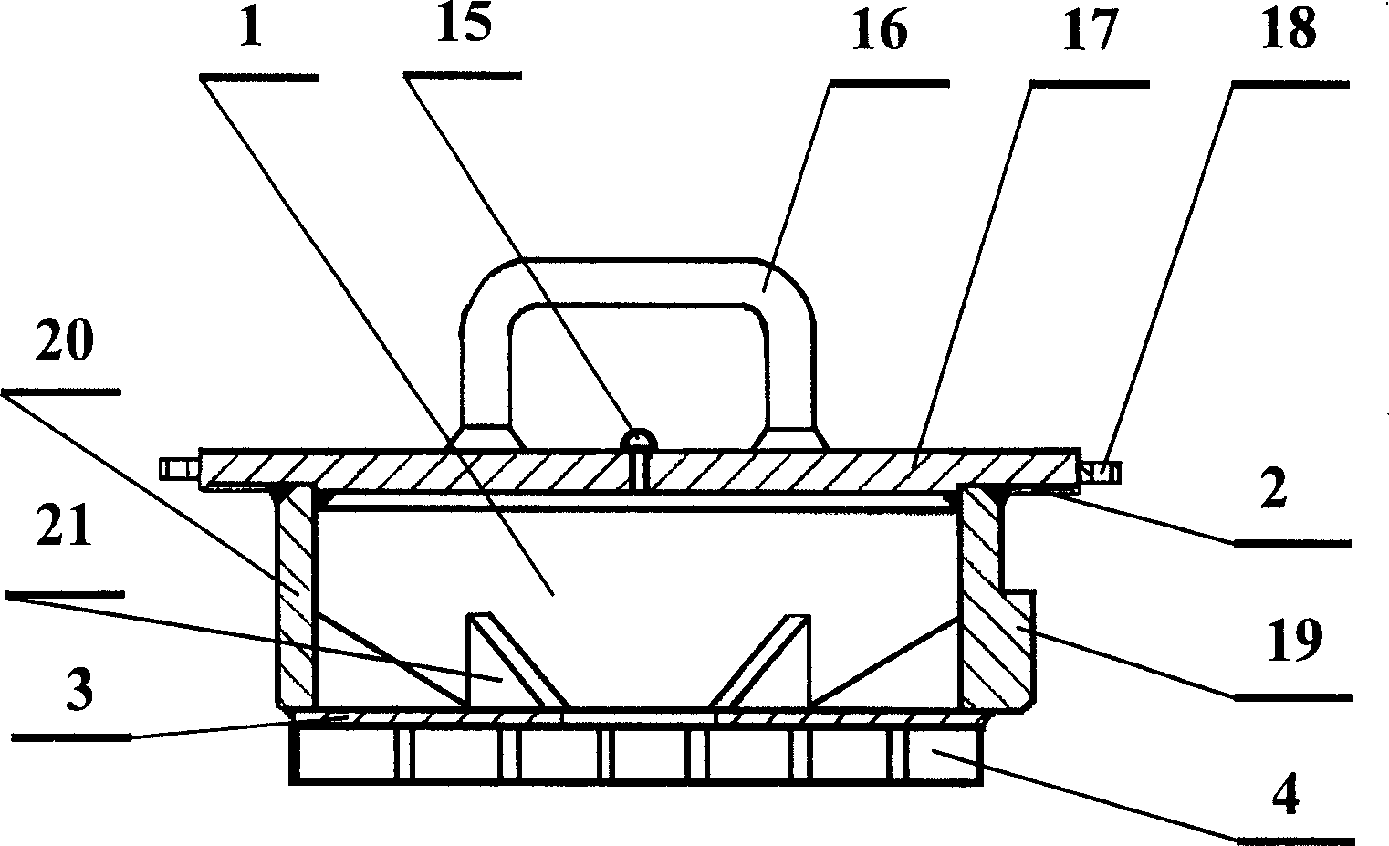
[0016] Such as figure 1 , figure 2 and image 3 As shown, the anti-explosion container has an upper cover 1, a cylinder body 10 and a fixed bracket 9 welded on the bottom of the cylinder body. The cylinder body 10 is composed of an outer cylinder 5 and an inner cylinder 6. The upper end of the outer cylinder 6 is open, and the lower end has a An integrated bottom head 13, the lower part of the inner cylinder 5 has a lower wave breaking plate 8, and the upper cover 1 is composed of a top cover plate 17 and a cylindrical cover wall 20, wherein the lower end of the cover wall 20 is provided with an upper wave breaking plate 3, and the cover wall 20 Splines 19 are arranged on the top, which can be connected with the spline collar 11 on the inner side of the upper port of the outer tube 6 , and the top cover plate 17 is equipped with explosion-venting bolts 15...


PUM


Abstract

The invention belongs to storage and transportation equipment for detonating materials (detonators), in particular to an anti-explosion container. The anti-explosion container includes an upper cover, a cylinder and a fixed bracket. It is characterized in that the cylinder is composed of an outer cylinder and an inner cylinder, wherein the outer cylinder is a cylinder with an open upper end and a closed lower end. The lower part of the inner cylinder is provided with a lower wave breaking plate. , the upper cover is composed of a top cover plate and a cover wall, wherein the lower end of the cover wall is provided with an upper wave dissipation plate, the cover wall and the upper port of the outer cylinder are connected by splines, and the top cover plate is provided with explosion-venting bolts. The invention can not only ensure safety when the detonating equipment and explosives are transported in the same vehicle, but also can seal the harmful gas generated by the explosion in the container in case of an explosion in the container, and discharge the harmful gas after it is transported to a suitable place. In order to avoid polluting the environment and causing casualties and damage to surrounding personnel and facilities. It has the advantages of flexible and convenient opening and closing, large loading capacity, long service life, and good anti-explosion and explosion-proof performance.

Description

technical field [0001] The invention belongs to storage and transportation equipment for detonating materials (detonators), in particular to an anti-explosion container. Background technique [0002] In the past, when transporting civil blasting materials, it was stipulated that the explosives and detonating materials (detonators, fuses, etc.) in the blasting materials must be loaded and transported in separate vehicles. manage. Therefore, at present, when transporting blasting materials, anti-explosion containers are often used to load detonating materials, and then the anti-explosion containers are installed on the vehicle for transporting explosives and the anti-explosion containers are separated from the explosives to realize the transportation of explosives and detonating materials in the same vehicle. Avoid detonating the explosives transported in the same vehicle in case the detonating equipment explodes, thereby improving the safety when the ...

Claims


Application Information

Patent Timeline
Patent Type & Authority Applications(China)
IPC IPC(8): F42B39/30
Inventor 蒋友明
Owner 蒋友明
Why Eureka
Try Eureka