Color splitting prism assembly

A dichroic prism and prism technology, applied in prisms, color TVs, color TV components, etc., can solve the problems of reducing the light efficiency of prism components, shortening the back focus, etc., to achieve shortening the back focus, reducing the optical path, and improving imaging The effect of accuracy

Inactive Publication Date: 2005-07-06
DELTA ELECTRONICS INC
View PDF0 Cites 6 Cited by
  • Summary
  • Abstract
  • Description
  • Claims
  • Application Information

AI Technical Summary

Problems solved by technology

[0005] However, although this system can achieve the effect of shortening the back focus and avoiding the disadvantages of the above-mentioned prism group 100, it will have a very large incident angle (=45deg) when the light beam is incident on the dichroic surface according to this design.
When the incident angle to the dichroic surface is too large, the polarization spectrum passing through the dichroic beam splitter will drift and affect the color purity after splitting, reducing the overall splitting efficiency of the prism group

Method used


Image

  • Color splitting prism assembly
  • Color splitting prism assembly
  • Color splitting prism assembly

Examples


Embodiment Construction

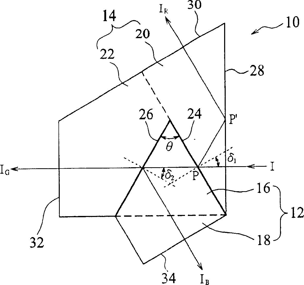
[0017] Figure 1A It is a schematic plan view showing a dichroic prism group 10 according to an embodiment of the present invention. The dichroic prism group 10 is used to separate the incident white light (white light) into three different color components, for example, the sequentially separated red light I shown in the figure R and Blu-ray I B , Green Light I G Three primary colors (primary color).

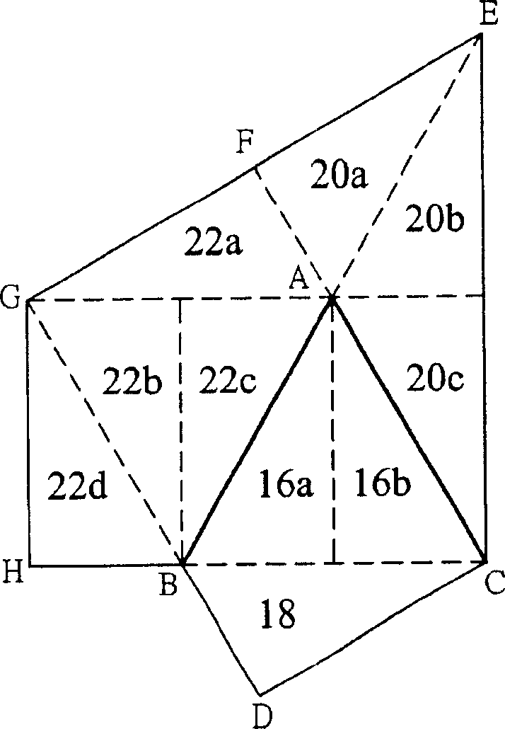
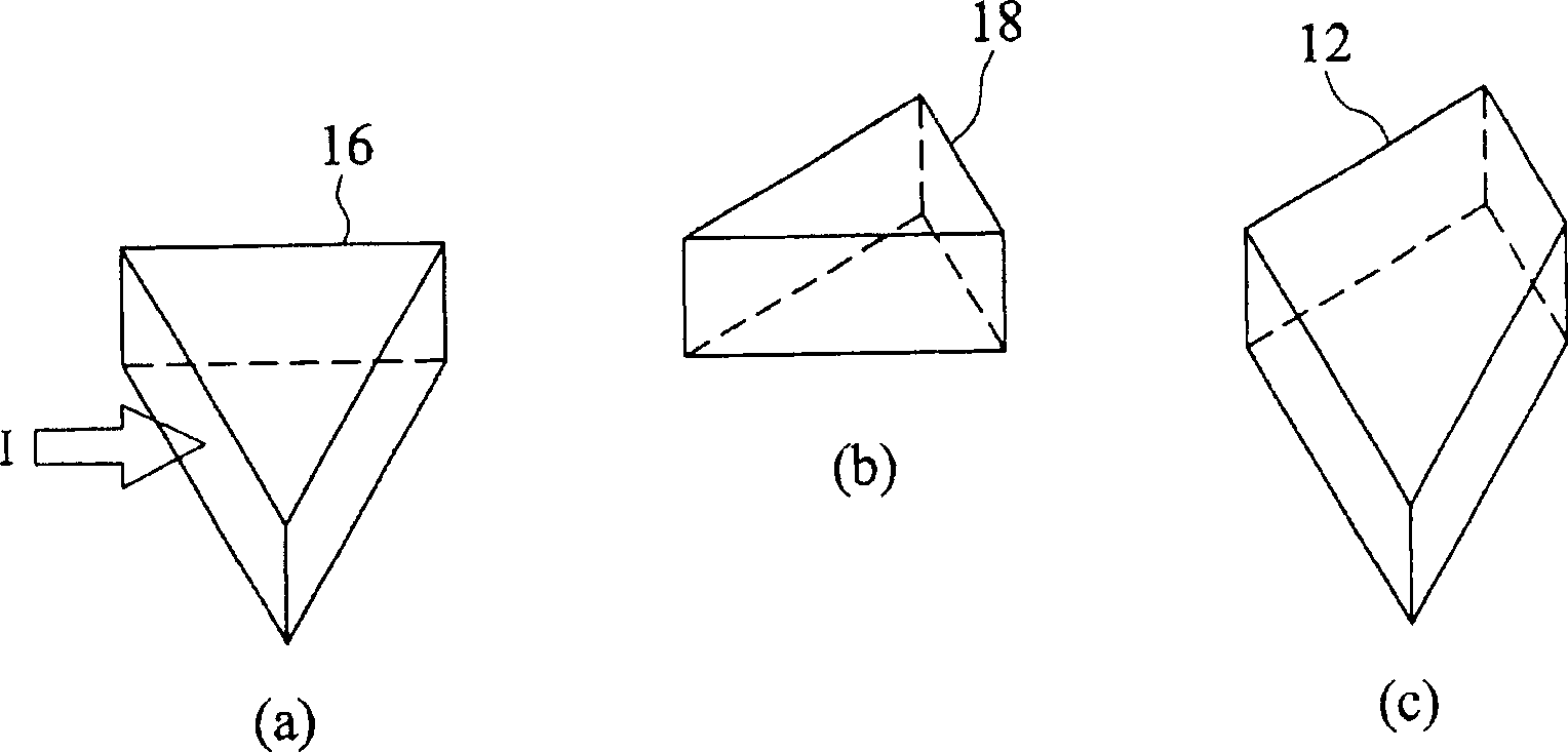
[0018] According to this embodiment, the dichroic prism group 10 is composed of two prism blocks 12 and 14 . The prism block 12 is in the shape of a quadrangular prism, which can be formed by combining a triangular prism 16 and a rectangular prism 18 . Figure 1B To show the three-dimensional views of the above-mentioned triangular prism (a), right-angle prism (b), and quadrangular prism (c) components, to clearly show the three-dimensional forms of various prisms used in the present invention. Such as Figure 1B As shown, the "triangular prism" in the present invention i...


PUM


Abstract

This invention relates to a color separation prism set with one first prism area and second prism area. The first prism area near two boundary surfaces form relative color frequency band double color filter lens and the second prism area is tightly connected to the first prism area through coating the double color filter lens. The second prism area is set to make the beam into the double color filter lens with an incidence angle less than thirty degrees and make the light path of each color in the prism after the separation prism.

Description

technical field [0001] The invention relates to a dichroic prism group, which is applied to a color projection system in a TV camera or a color projection display. Background technique [0002] Figure 7 It is a schematic diagram showing a Philips prism assembly 100 for separating incident light into three primary colors of red (R), blue (B) and green (G) in a conventional optical system. Such as Figure 7 As shown, the prism set 100 includes three prisms 102 , 104 and 106 , and dichroic surfaces 108 and 110 coated with a dichroic filter layer. The prisms 102 and 104 are separated by an air gap 114 . When the incident light I enters the prism group 100, the dichroic surface 110 filters out and reflects the red light I R , while Blu-ray I B and green light I G can penetrate the surface 110, the reflected red light I R After being reflected by an inner surface of the prism 102, it enters into a liquid crystal light valve (LCLV) 112R. Next, the red light I has been filtere...

Claims


Application Information

Patent Timeline
Patent Type & Authority Applications(China)
IPC IPC(8): G02B5/04G02B5/20G02B27/10H04N5/225H04N9/31
Inventor 贺方涓
Owner DELTA ELECTRONICS INC
Why Eureka
Try Eureka