Air-conditioner for vehicles

A technology for air-conditioning devices and vehicles, which is applied to vehicle components, transportation and packaging, and air handling equipment, etc. It can solve problems such as difficult installation space and achieve the effect of easy assembly

Inactive Publication Date: 2005-07-13
DENSO CORP
View PDF1 Cites 19 Cited by
  • Summary
  • Abstract
  • Description
  • Claims
  • Application Information

AI Technical Summary

Problems solved by technology

Compared with such small special vehicles, in trucks, in order to improve the driving performance of the vehicle, the shape of the front side of the roof part of the vehicle and the ceiling part of the vehicle is generally formed into a streamlined shape, so that the arrangement row is formed on this part. The installation space required for outlet and discharge ducts is very difficult

Method used


Image

  • Air-conditioner for vehicles
  • Air-conditioner for vehicles
  • Air-conditioner for vehicles

Examples


no. 1 example

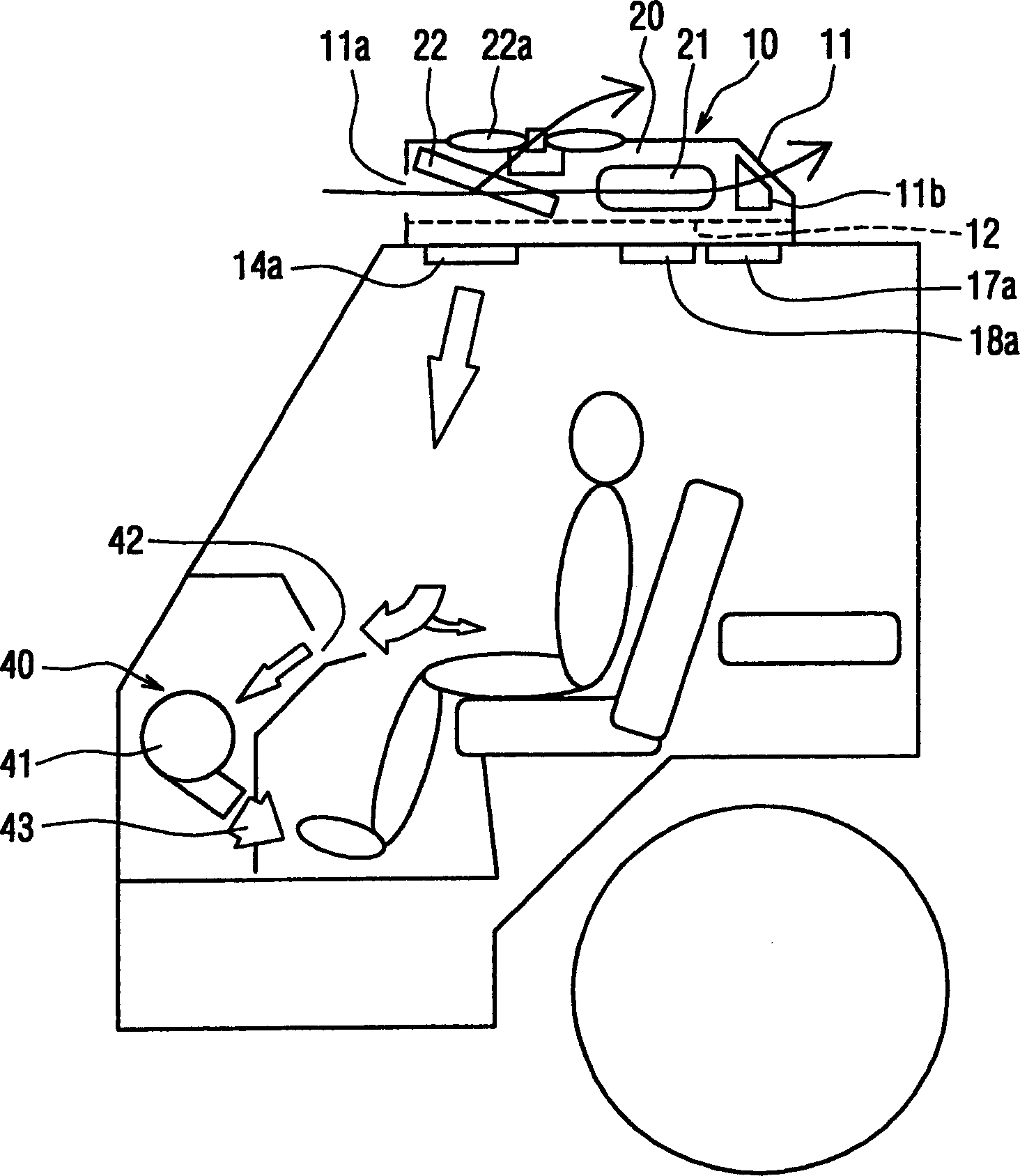
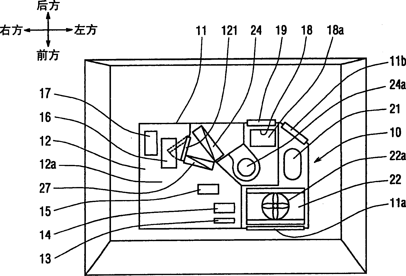
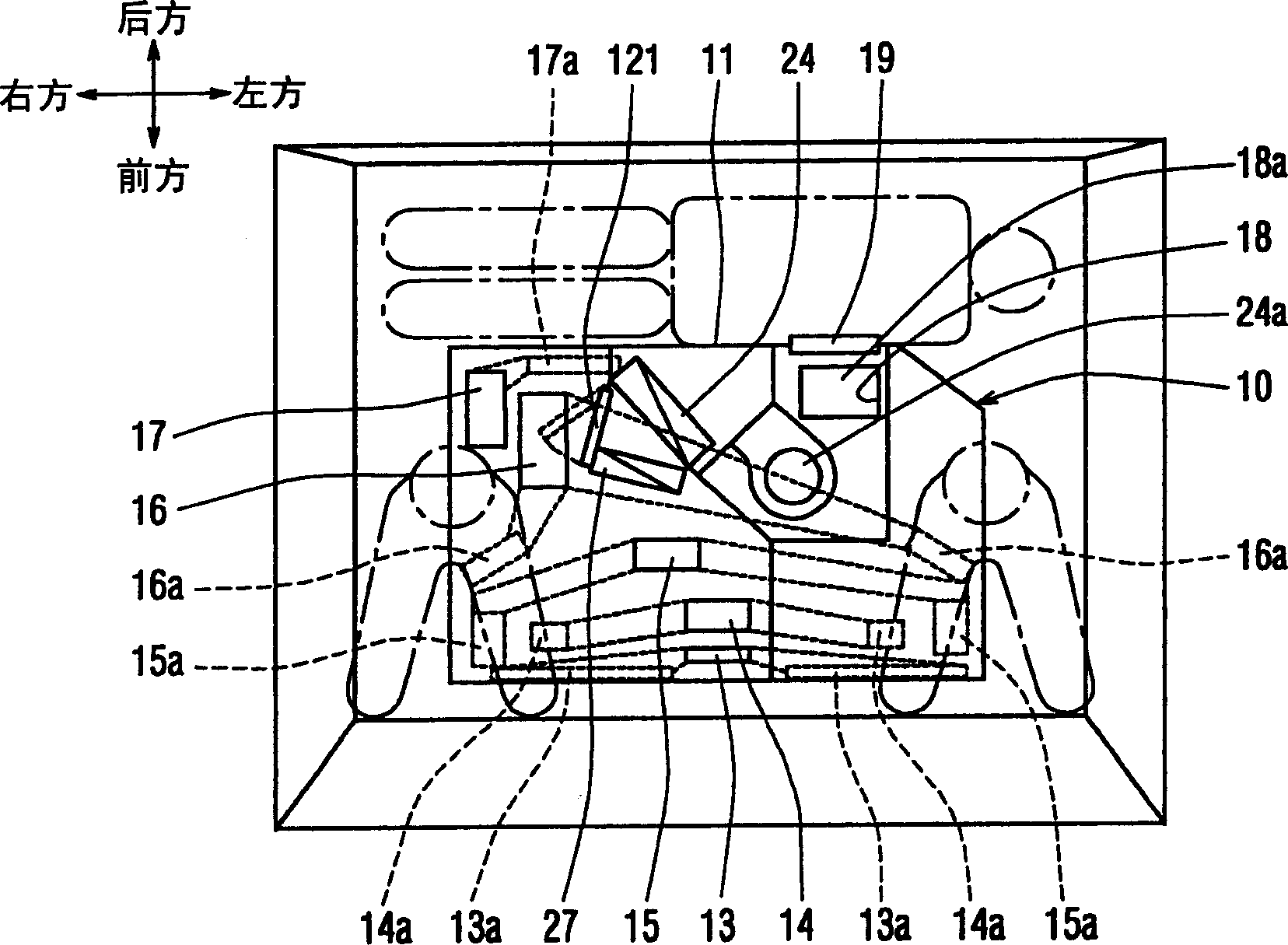
[0016] Such as Figure 1~3 As shown, the vehicle air conditioner of the present embodiment consists of an air conditioning unit 10 disposed on the roof of the vehicle, a plurality of outlets 13a to 17a disposed on the ceiling of the vehicle, a suction port 18a for inhaling the air in the vehicle interior, and an air conditioner disposed on the instrument panel of the vehicle. The air supply unit 40 in the tray is formed. The air conditioning unit 10 is a unit that blows air-conditioning air to the plurality of discharge ports 13a to 17a, and the air-conditioning air is sucked into the air in the vehicle interior through the air intake port 18a to adjust the temperature. The air-conditioning unit divides the inside of the air-conditioning box 11 into an upper layer and a lower layer through a partition 12 . Refrigeration cycle devices 20 such as a compressor 21 and a condenser 22 are integrally provided in the upper layer, and a plurality of discharge openings 13 to 17 opening...

no. 2 example

[0055] In the first embodiment, the air blowing unit 40 is provided in the dashboard at the front of the vehicle. However, it may also be provided in a door trim of a vehicle. Specifically, if Figure 5 As shown, air blowing units 40a are respectively arranged in the left and right door trims of the vehicle, the upper end suction port 42 is arranged in the air blowing range where air-conditioning air can be blown out from the side defroster outlet 15a, and the lower end outlet 43 blows air toward the passenger's feet. . Furthermore, the air blower 41 is electrically connected to the control device 30 so as to be linked and controlled when it is in a blowing mode in which the side defroster opening 15 is opened.

[0056] Therefore, similar to the above-mentioned first embodiment, the warm air blown out from the discharge port 15a of the suction side defroster is blown to the passenger's feet, and the comfort of the passenger will not be impaired during heating. In addition, ...

no. 3 example

[0058] In the above-described embodiments, the refrigeration cycle device 20 provided in the air conditioning unit 10 is constituted by a heat pump cycle device that switches the flow direction of the refrigerant according to the cooling operation and the heating operation. but if Image 6 As shown, it is also possible to use the refrigeration cycle device 20 for cooling operation only, and the heater core 50, which is a heating heat exchanger using cooling water of the vehicle engine as a heat source, on the air flow downstream side of the evaporator 24. Combination, as a device for cooling operation and heating operation.

[0059] It should be noted that, at this time, an accumulator 25 a is provided between the condenser 22 and the pressure reducer 23 , and an expansion valve is provided in the pressure reducer 23 . As a result, the safety problem of the heating operation does not arise during the running of the vehicle. It is very difficult to heat the vehicle for a long...


PUM


Abstract

The invention relates to a vehicle air-conditioning device for adjusting the air in the vehicle, which comprises: an air-conditioning unit (10), an evaporator (24) and a heat exchanger (27) for heating, which are arranged on the roof of the vehicle. In the above-mentioned air conditioning unit (10), a plurality of discharge openings (13-17) that open air passages corresponding to a plurality of blowing modes; are provided on the vehicle ceiling to communicate with the above-mentioned discharge openings (13-17) respectively A plurality of discharge outlets (13a-17a) connected in a manner to blow temperature-regulated air-conditioning air into the vehicle; among the above-mentioned multiple discharge outlets (13a-17a), the heating exhaust for blowing warm air to the lower part of the vehicle interior an outlet (14a); and an air blowing unit (40) for sucking warm air blown out from the heating outlet (14a) and blowing it toward the feet of passengers.

Description

technical field [0001] The present invention relates to a vehicle air conditioner mounted on a vehicle such as a truck, and more particularly to a vehicle air conditioner unit provided on the roof of the vehicle, and air-conditioning air is blown from the ceiling portion of the vehicle during heating. Background technique [0002] Conventionally, a method described in JP09-249020A has been known as a method of installing an air conditioning unit in which an air passage is formed on a vehicle ceiling or a roof. This air conditioner for vehicles can adjust the air in the cab of small special vehicles such as construction machinery. In this device, a plurality of discharge ports and discharge ducts connected to these discharge ports for introducing air-conditioning air from an air-conditioning unit are provided on the ceiling above the heads of passengers. [0003] In the case of a special vehicle, a discharge duct having a discharge port for a foot defroster that blows air do...

Claims


Application Information

Patent Timeline
Patent Type & Authority Applications(China)
IPC IPC(8): B60H1/00B60H1/24B60H1/32
CPCB60H1/00899B60H1/247
Inventor 梅尾忠司上野幸雄平尾繁典
Owner DENSO CORP
Why Eureka
Try Eureka