
Injection device

A technology of injection device and sealing element, applied in syringes, auto-injectors, ampoule syringes, etc., can solve problems such as battery damage, leakage, damage to electronic equipment, etc.

Inactive Publication Date: 2010-06-16
TECPHARMA LICENSING AG
View PDF5 Cites 0 Cited by
  • Summary
  • Abstract
  • Description
  • Claims
  • Application Information

AI Technical Summary

Problems solved by technology

[0004] However, a small portion of the substance dispensed by the injection pen may leak, for example through an opening provided on the contact element 10 into a so-called E-module M or into a circuit or circuitry that evaluates the movement of the contact element 10 board, which could damage the electronic
Similarly, if the injection pen is placed in a refrigerator in order to ensure that the substance to be dispensed in the injection pen is well preserved, when the air is cooled and compressed, the moisture in it can easily enter the electronic device, and the electronic device or Batteries set up to run electronic devices can be damaged

Method used


Image

  • Injection device
  • Injection device
  • Injection device

Examples


Embodiment Construction

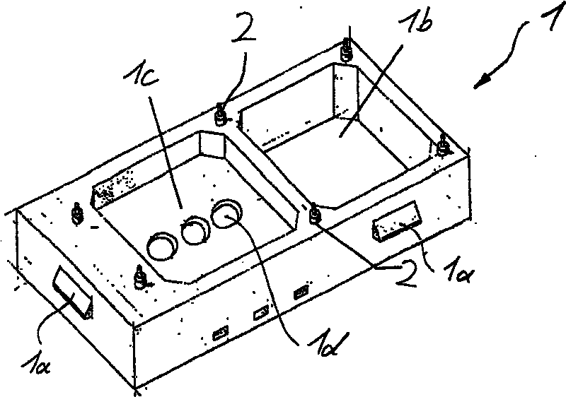
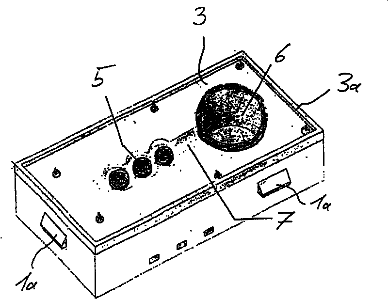
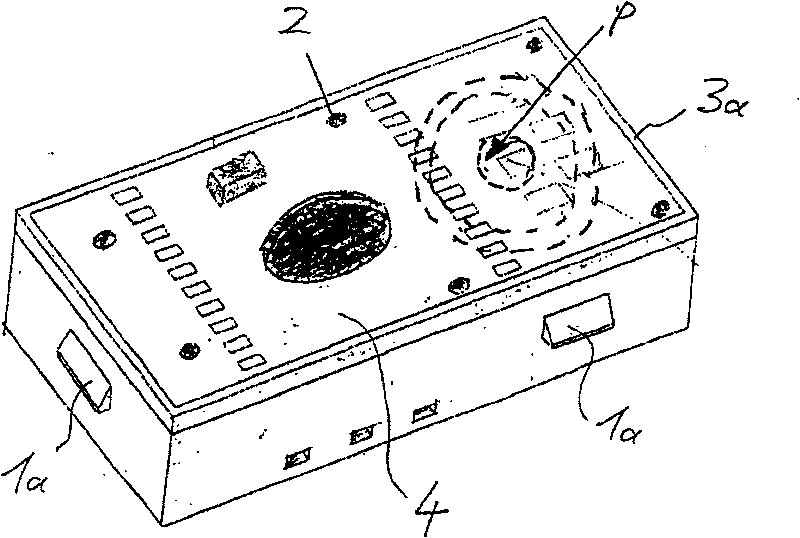
[0021] figure 1 A module base shown is used as a housing, wherein additionally connected locking protrusions 1a for locking to the module window 9, such as Figure 4 As shown, connected to the outer shell, the interior of the module base 1 includes two compartments or spaces 1b and 1c, wherein, for example, a battery can be inserted into the space 1b, and the space 1c is accessed through the hole 1d provided on the module base 1. The pressure movement of the contact element and / or the pressure plate 10 is transmitted. Bolts 2 spaced apart from each other are arranged on the top shell of the module base, such as figure 2 and 3 As shown, a sealing element 3 and a circuit board 4 are arranged on the spaced bolts.

[0022] figure 2 shown is figure 1 In the module base, a silicone gasket is provided as a sealing element 3, wherein the silicone gasket 3 includes a hole corresponding to a slightly larger outer diameter separating the lower part of the bolt 2, so that the sil...


PUM


Abstract

The invention relates to a sealing element (3) of at least one component in an injection device which is used for seamed control of drug ingredients in reagents, wherein, the sealing element seals atleast one electrical component (4). The invention also relates to a control device including the sealing element.

Description

technical field [0001] The present invention relates to an injection device, in particular to a sealing element on a control device (such as an injection device or an injection pen) used to control a drug component in a medicament. Background technique [0002] An example of a known injection device is described in WO 03 / 053499. [0003] Figure 5 Shown is a longitudinal sectional view of the rear end of a known injection device. A piston rod K pushes a piston (not shown) to advance along the longitudinal axis L towards the container outlet (not shown), wherein the range of movement of the piston rod K is limited by rotating the positioning element E, and by pressing The positioning element E triggers. In order to show the user the amount of medicine he has set by turning the positioning element E, a display element A is provided on which the quantity value of the set dose is shown, wherein the set dose value is determined, it is established on On the basis of the movemen...

Claims


Application Information

Patent Timeline
Patent Type & Authority Patents(China)
IPC IPC(8): A61M5/31A61M5/24A61M5/178A61M5/20F16J15/06F16J15/10H05K5/06
CPCA61M5/20F16J15/106
Inventor M·霍夫斯特特尔
Owner TECPHARMA LICENSING AG
Learn More