Electromagnetic drum brake

A drum brake and electromagnetic technology, applied in the direction of drum brakes, mechanically driven drum brakes, brake types, etc., can solve the problem of expanding the gap between the armature and the magnetic pole surface of the magnetic field core

Inactive Publication Date: 2005-07-27
OGURA CLUTCH CO LTD
View PDF3 Cites 12 Cited by
  • Summary
  • Abstract
  • Description
  • Claims
  • Application Information

AI Technical Summary

Problems solved by technology

[0011] Also, in conventional electromagnetic drum brakes, when the brake linings are worn, t

Method used


Image

  • Electromagnetic drum brake
  • Electromagnetic drum brake
  • Electromagnetic drum brake

Examples


Embodiment Construction

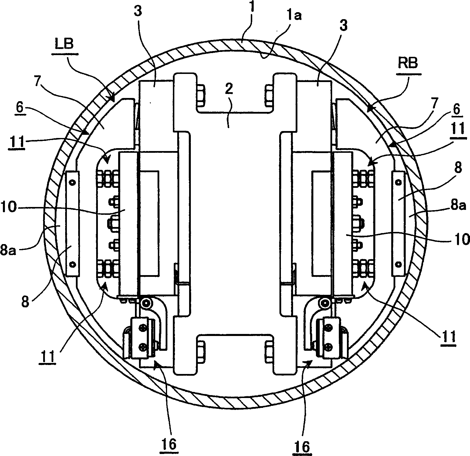
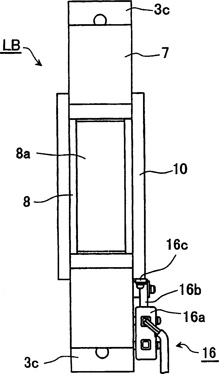
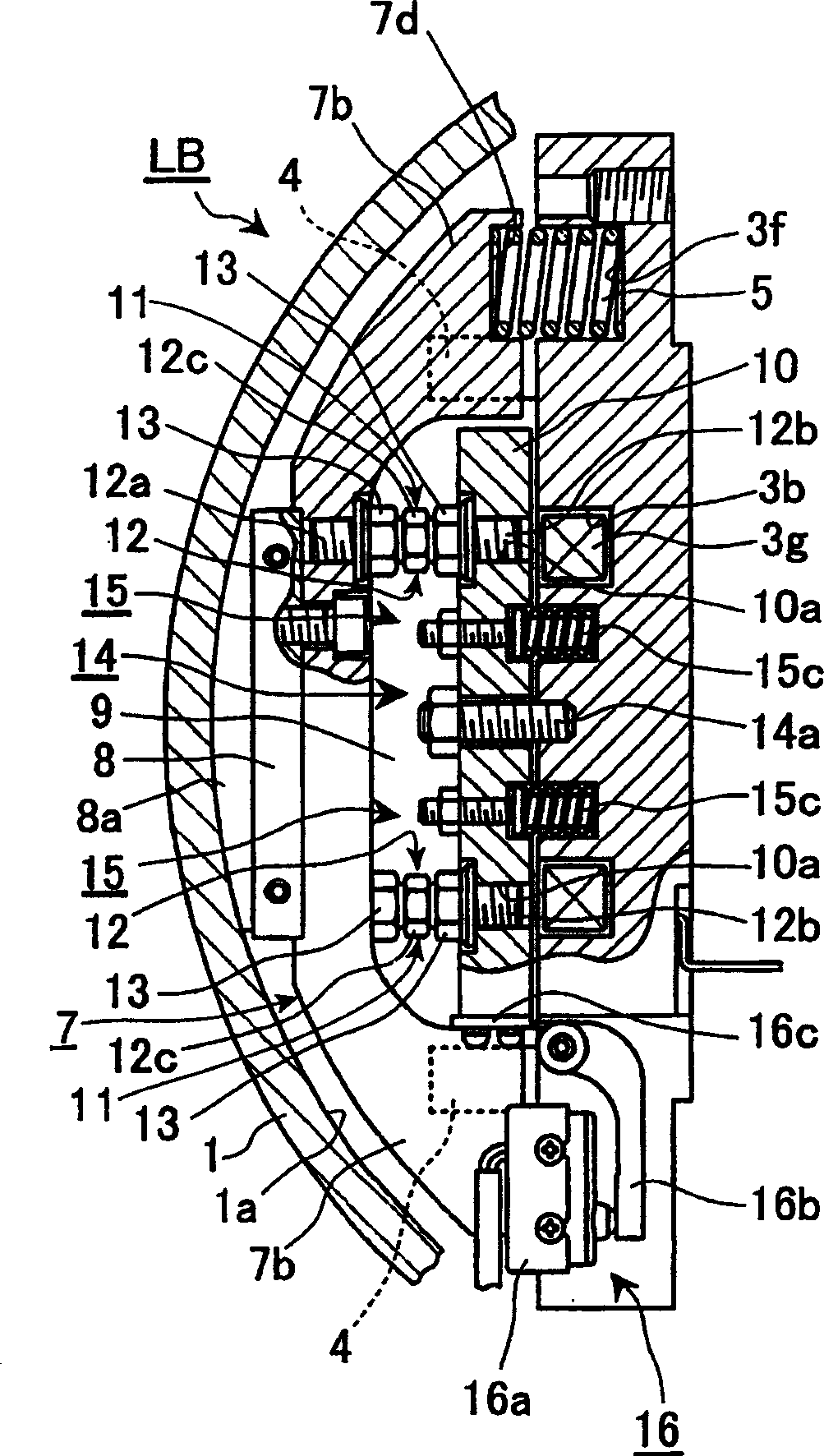
[0023] Below, refer to Figure 1 to Figure 8 An electromagnetic drum brake according to an embodiment of the present invention will be described. As the electromagnetic drum brake of this embodiment, a brake for holding a hoist for an elevator is shown. In addition, in figure 1 2001-72358 A shows a state where two electromagnetic drum brakes are assembled inside the motor rotating body (rotating body 19 ) of JP-A-2001-72358.

[0024] Hoists for elevators, such as figure 1 As shown, in the circumferential direction of the cylindrical braking surface 1a of the brake drum 1, the left electromagnetic drum brake LB and the right electromagnetic drum brake RB are assembled at a distance of 180 degrees (facing each other). . In each electromagnetic drum brake LB, RB, the field core 3 is arranged on the same axis as the brake drum 1 and attached to both sides of a support plate 2 fixed to a fixing member (not shown). The electromagnetic drum brakes LB and RB differ only in that t...


PUM


Abstract

An electromagnetic drum brake, comprising a field core (3) having support parts (3c) formed therein, brake shoes (6) having leg parts (7b) formed therein, armatures (10) stored between the brake shoes (6) and the field core (3) and connected to the brake shoes (6), and a plurality of braking springs (5) installed between the support part (3c) of the field core (3) and the end faces of the leg parts (7b) of the brake shoes (6), wherein the armatures (10) are connected to the brake shoes (6) with adjusting bolts (12) having right-hand threads (12a) formed on one sides thereof and left-hand threads (12b) formed on the other sides.

Description

technical field [0001] The present invention relates to a de-energized electromagnetic drum brake most suitable for use as a brake for a motor such as a hoist for an elevator or an industrial robot. Background technique [0002] There are proposals to use electromagnetic drum brakes as brakes for braking the rotating body of the hoist drive motor for braking elevators or for holding the rotating body in a stopped state (see JP-A-2001-72358, JP-A-2000- 232754 bulletin, JP-A 2001-343033 bulletin). [0003] In the hoisting device for an elevator proposed as the second embodiment of JP-A-2001-72358, an eccentric gear having an internal gear with a cable groove formed on the outer circumference is arranged on the right side of the fixing member. Swing reducer. In addition, a drive motor having a motor coil provided on the side of the fixed member and a permanent magnet provided on the input shaft side of the reducer is arranged on the left side of the fixed member. The permane...

Claims


Application Information

Patent Timeline
IPC IPC(8): F16D65/18F16D51/12F16D59/02F16D65/14F16D65/22F16D65/28F16D65/46
CPCF16D59/02F16D65/22F16D2121/22
Inventor 高桥桂三广田教彦川俣贵义
Owner OGURA CLUTCH CO LTD
Why Eureka
Try Eureka