Vehicle brake device

A brake device and vehicle technology, applied in the direction of brakes, brake components, vehicle components, etc., can solve the problem of failure to detect the failure of the main system, and achieve the effect of suppressing the reduction of braking force

Active Publication Date: 2013-06-05
ADVICS CO LTD
View PDF5 Cites 1 Cited by
  • Summary
  • Abstract
  • Description
  • Claims
  • Application Information

AI Technical Summary

Problems solved by technology

Also, in the invention described in Patent Document 2, although failure of the vacuum booster can be detected, failure of the main system cannot be detected.

Method used


Image

  • Vehicle brake device
  • Vehicle brake device
  • Vehicle brake device

Examples


Embodiment Construction

[0020] Embodiments of the present invention will be described below with reference to the drawings. In addition, each drawing is a schematic diagram, and does not prescribe the dimension to a detailed structure.

[0021] (Structure of vehicle brake device)

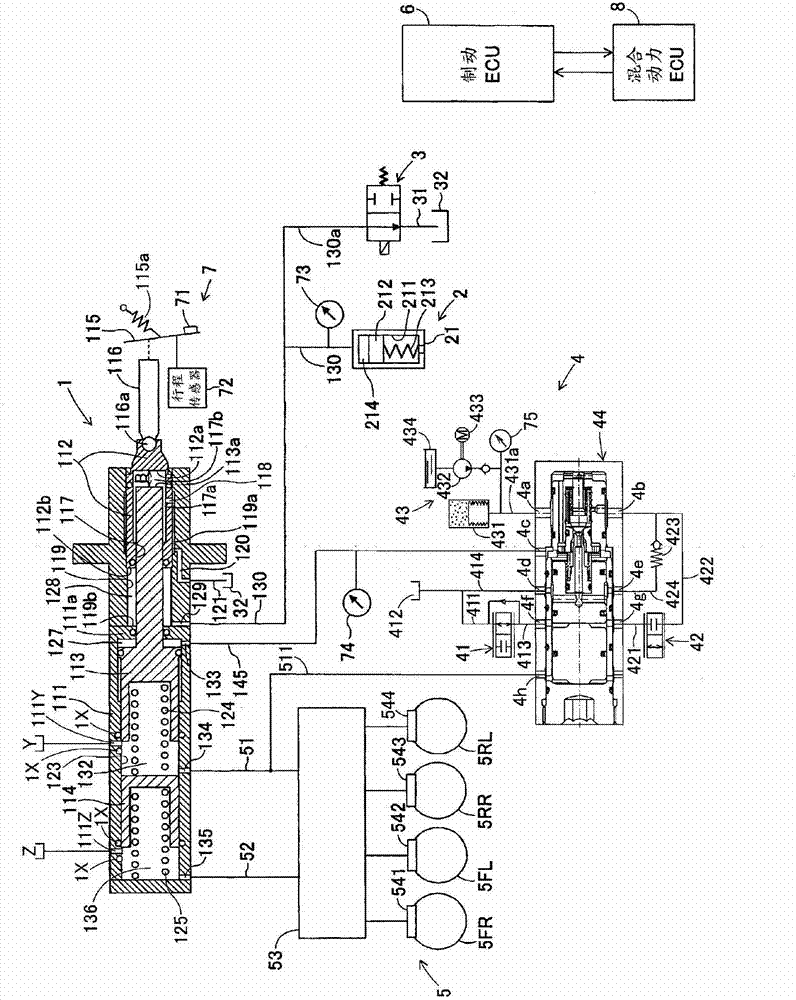
[0022] figure 1 A schematic configuration diagram of a vehicle brake device according to the present embodiment is shown. The brake device for a vehicle according to the present embodiment includes: a master cylinder 1 having master pistons 113, 114 arranged at a distance B from the input piston 112 in the advancing direction of the input piston 112, And relative to the input piston 112, it slides independently along the axis direction; the reaction force generating device 2, the reaction force generating device 2 makes the reaction force chamber 128 generate the reaction force pressure corresponding to the movement amount of the input piston 112; the switching valve 3, the switching The valve 3 is provided in the open ...


PUM


Abstract

A vehicle brake device includes a failure detection means for driving the master piston only by the operation force of the brake operation member along with the operation of the brake operation member, thereby to detect a failure of a master system, when a master cylinder pressure correlation value correlated to the master cylinder pressure is less than a predetermined value, in a case where an operation amount of the brake operation member is a predetermined amount or in a case where the operation force of the brake operation member is a predetermined force; and a driving control means for driving the master piston by force corresponding to the servo pressure in the servo chamber generated by the servo pressure generation portion, when the operation amount of the brake operation member is greater than a predetermined amount, or when the operation force of the brake operation member is greater than a predetermined force, in the operation of the brake operation member in which the failure detection means detects the failure of the master system.

Description

technical field [0001] The present invention relates to a vehicle brake device that controls a braking force applied to a vehicle based on a driver's brake operation amount. Background technique [0002] As an example of a vehicle control device that controls the braking force applied to the vehicle based on the driver's brake operation amount, for example, Japanese Patent Application Laid-Open No. 2010-167915 (Patent Document 1), Japanese Patent Laid-Open No. 9-328069, etc. A brake device for a vehicle disclosed in the gazette (Patent Document 2). In these braking devices for vehicles, the input piston and the pressurizing piston are kept apart at a predetermined interval (stroke), and the wheel cylinder is given control based on accumulator and linear valve according to the movement of the input piston. Hydraulic braking force. In such a vehicle brake device, a main system including a master cylinder constituting a pressurizing piston and the like plays an important role...

Claims


Application Information

Patent Timeline
Patent Type & Authority Applications(China)
IPC IPC(8): B60T17/18
CPCB60T8/4077B60T17/221B60T13/147B60T13/58
Inventor 坂田康典
Owner ADVICS CO LTD
Why Eureka
Try Eureka