Vehicular brake device

A technology for braking devices and vehicles, which is applied in the direction of braking transmission devices, automatic starting devices, brakes, etc., and can solve the problems of complicated device structures and increased costs

Inactive Publication Date: 2019-11-15
ADVICS CO LTD
View PDF7 Cites 0 Cited by
  • Summary
  • Abstract
  • Description
  • Claims
  • Application Information

AI Technical Summary

Problems solved by technology

[0007] However, such an electric parking brake device needs to have the required strength to achieve the target torque, and the cost for improving reliability may increase
In

Method used


Image

  • Vehicular brake device
  • Vehicular brake device
  • Vehicular brake device

Examples


no. 1 approach

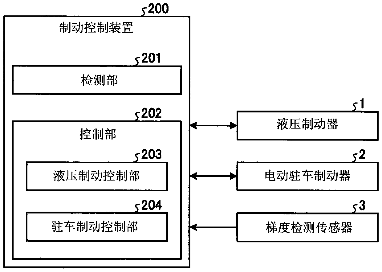
[0085] Next, the operation of the brake control device 200 of the first embodiment will be described in more detail.

[0086] Figure 4 It is a flowchart showing an example of a series of processes executed by the brake control device of the first embodiment.

[0087] First, the brake pedal is turned on by the driver (step S11), if the electric parking brake (in Figure 4 Marked as EPB) switch is turned on (step S12), then the braking control device 200 is based on the output of the gradient detection sensor 3 of acceleration sensor, gyroscope sensor, etc., and detects the inclination of the front and rear direction of the vehicle, that is, the gradient of the road surface (step S13 ).

[0088] Next, based on the detected slope of the vehicle in the front-rear direction, that is, the gradient of the road surface, it is determined whether or not the vehicle is parked on a slope (step S14 ).

[0089] In the determination of step S14, when the vehicle is parked on a slope (ste...


PUM


Abstract

This vehicular brake device is provided with: a hydraulic braking unit capable of controlling hydraulic pressures and generating hydraulic braking forces, independently for front and rear wheels of avehicle; a pressing lever which presses a braking shoe against a drum provided to the rear wheels of the vehicle, the braking shoe being movable relative to the drum; an electric actuator which drivesthe pressing lever; a gradient detection unit which detects the gradient of a road surface; and a control unit which, when the vehicle is parked, performs control to reduce the hydraulic pressure, atthe fluid-pressure braking unit corresponding to the front wheels, to a predetermined pressure corresponding to the gradient of the road surface, and performs control to cause the electric actuator to drive the pressing lever after completion of the pressure reduction.

Description

technical field [0001] The present invention relates to a brake device for a vehicle. Background technique [0002] In the past, in order to reduce the load caused by repeated generation of the hydraulic braking force using the hydraulic brake and the parking braking force using the electric parking brake on the specified wheels, a technology has been proposed that reduces the hydraulic pressure when the electric parking brake is activated. Braking force. [0003] However, in a vehicle equipped with an electric parking brake with a drum brake, there is a concern that when the brake pad is pressed when the brake pad is switched from the hydraulic brake to the electric parking brake when parking on a gradient road surface, In the state of the drum, as the hydraulic pressure of the front wheel is decompressed, the brake pad moves relative to the drum, and the pressing force by the pressing lever decreases, thereby reducing the braking force, and the required braking force cann...

Claims


Application Information

Patent Timeline
IPC IPC(8): B60T13/74B60T7/12
CPCB60T7/12B60T13/74
Inventor 冈村隼古一克也
Owner ADVICS CO LTD
Why Eureka
Try Eureka