Pneumatic amplifier

A pneumatic amplifier and air chamber technology, applied in engine components, physical quantity changers, fluid pressure actuating devices, etc., can solve problems such as not very ideal, and achieve the effect of reducing dead zone, speeding up stabilization, and reducing aperture

Active Publication Date: 2014-10-08
YAMATAKE HONEYWELL CO LTD
View PDF5 Cites 0 Cited by
  • Summary
  • Abstract
  • Description
  • Claims
  • Application Information

AI Technical Summary

Problems solved by technology

Also, it is not ideal because it leads to an increase in the size of the air amplifier

Method used


Image

  • Pneumatic amplifier
  • Pneumatic amplifier
  • Pneumatic amplifier

Examples


Embodiment Construction

[0055] Hereinafter, embodiments of the present invention will be described in detail based on the drawings.

[0056] [Embodiment 1: Single-acting type]

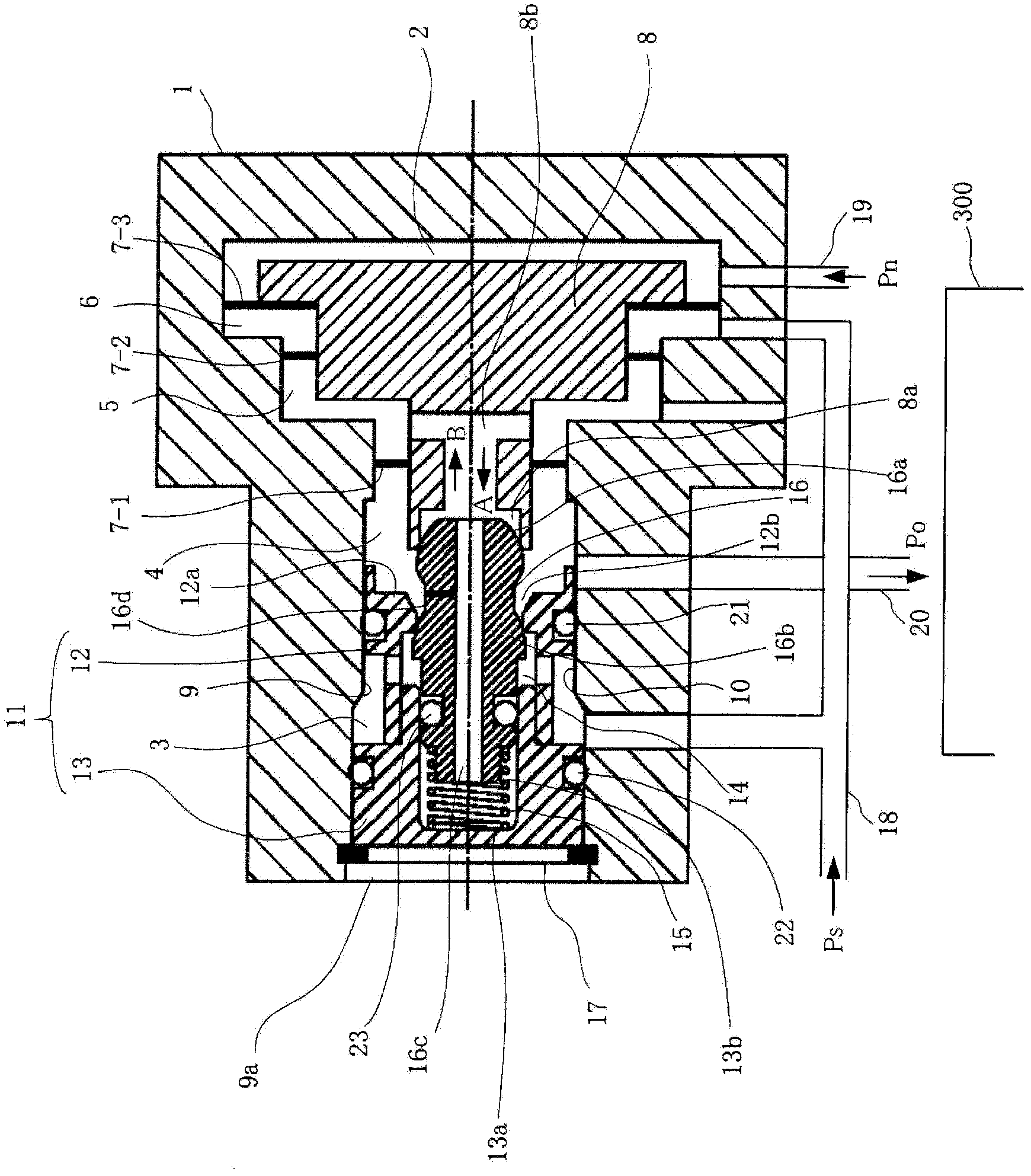
[0057] figure 1 It is a diagram showing the configuration of an embodiment of the pneumatic amplifier according to the present invention. The pneumatic amplifier is a single-acting type. In the figure, 1 is a housing, and an input air pressure chamber 2, a supply air pressure chamber 3, an output air pressure chamber 4, an exhaust chamber 5, and a bias chamber 6 are provided in the housing 1.

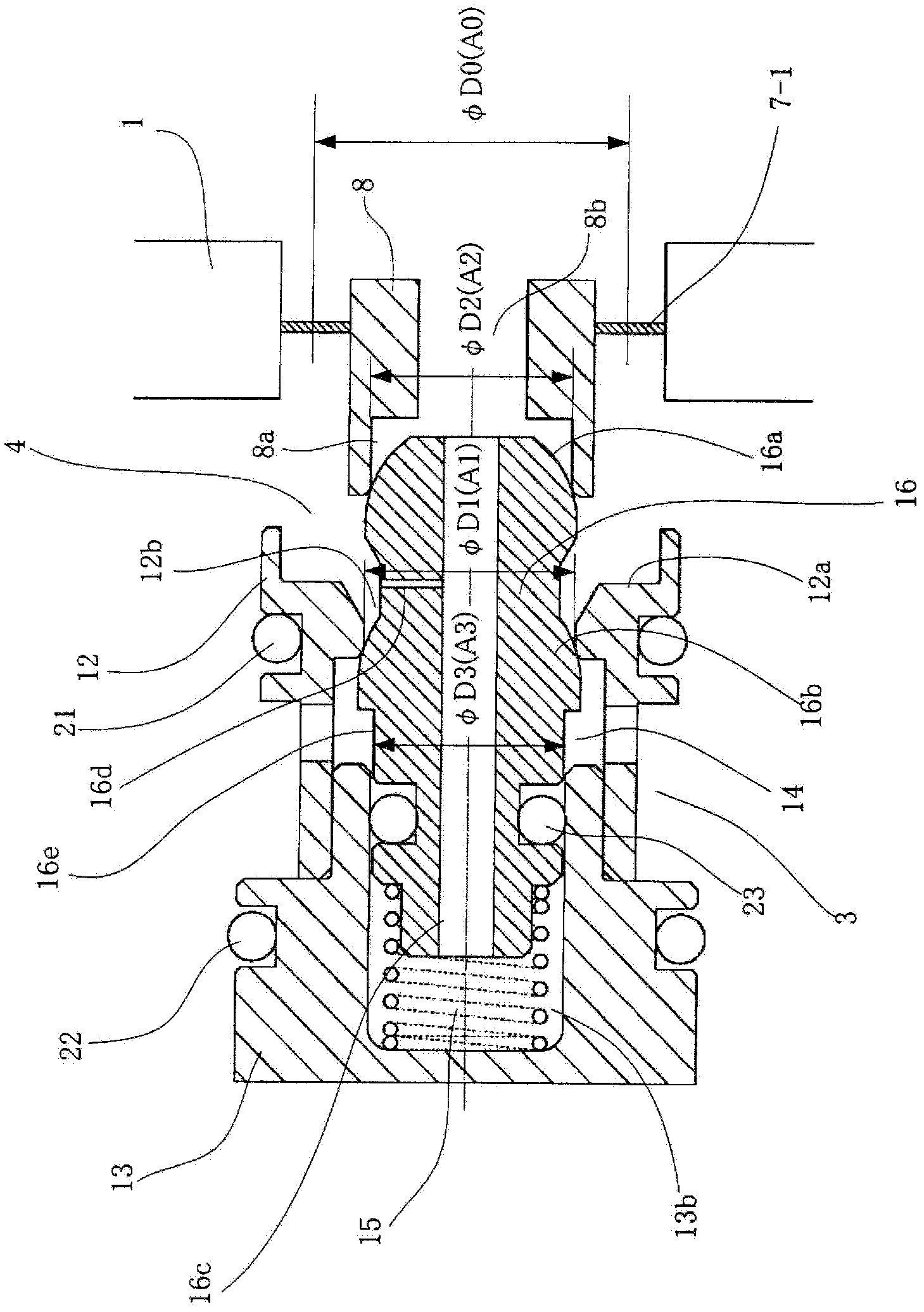
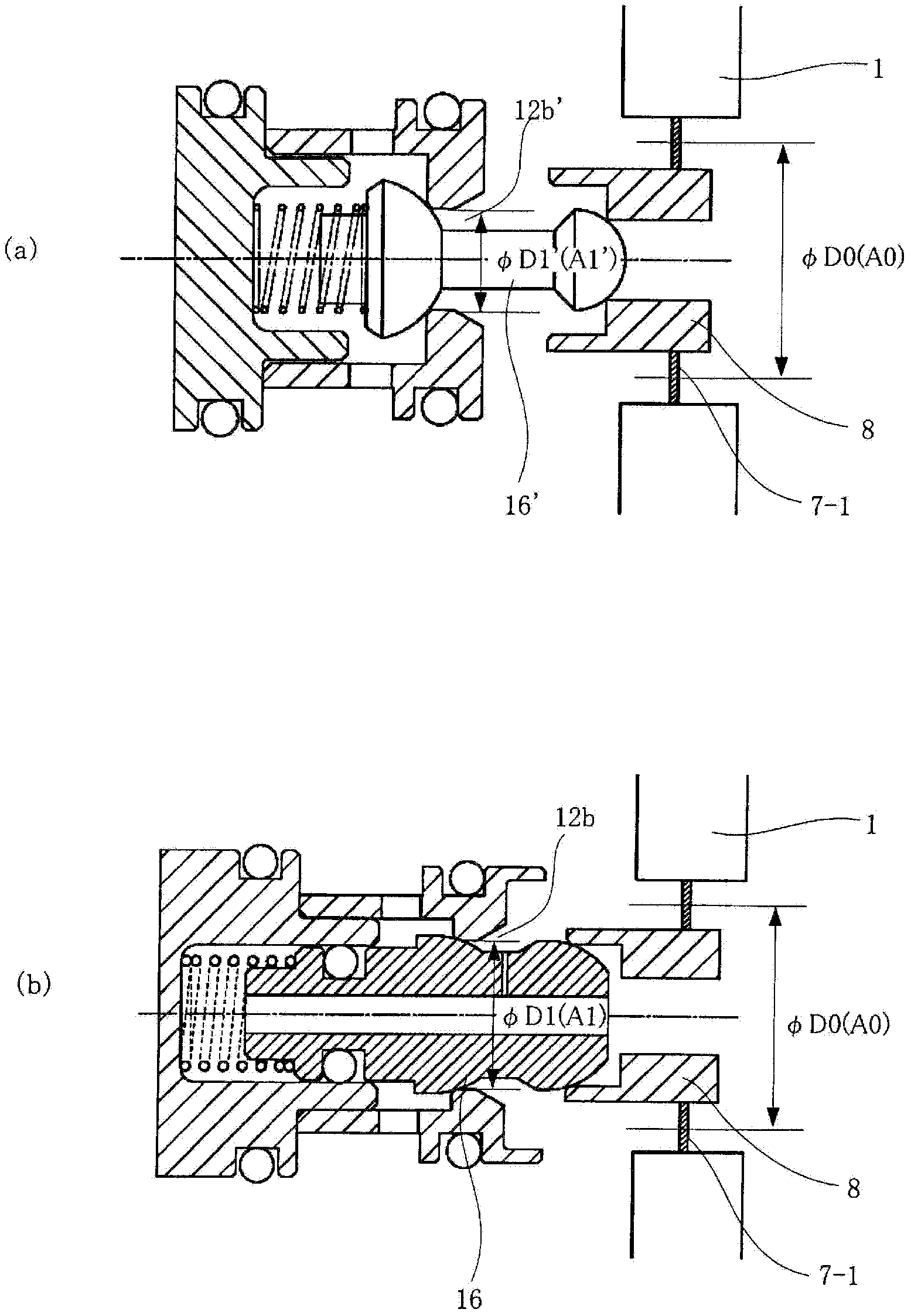
[0058] In the housing 1, the exhaust chamber 5 is adjacent to the output pneumatic chamber 4 via the first diaphragm 7-1, and adjacent to the bias chamber 6 via the second diaphragm 7-2. In addition, the input pneumatic chamber 2 is adjacent to the bias chamber 6 via the third diaphragm 7-3. The first to third diaphragms 7-1 to 7-3 are provided between the housing 1 and the valve plug (moving body) 8. The valve plug 8 is movable in the A ...


PUM


Abstract

A poppet valve assembly is structured divided into a seat portion and a seat retaining portion. A spring is contained within an interior space between the seat portion and the seat retaining portion, where a poppet valve is held between the seat portion and the seat retaining portion in a state biased by the spring. The poppet valve is provided with a through hole for connecting a chamber that contains the spring and a discharge air duct of a spool, and a fine connecting duct for connecting the through hole and an output air pressure chamber. The chamber that contains the spring is separated from a supply air pressure chamber by an O-ring.

Description

Technical field [0001] The present invention relates to a pneumatic amplifier used in a positioner or the like for controlling the opening degree of a pneumatic regulating valve (valve). Background technique [0002] In the past, positioners were used for valve drive control, process automation, and other general industrial equipment drive control. By installing the positioner on the valve, the valve opening control became possible. [0003] Figure 20 The configuration of the main part of the positioner capable of controlling the opening degree of the valve is shown. In the figure, 100 is a positioner. The positioner 100 has: an electro-pneumatic conversion unit 101 that converts a valve opening signal sent by an electrical signal from the upper controller 200 into a pneumatic signal Pn, and a The air pressure signal (input air pressure) Pn converted by the part 101 is amplified and output to the pneumatic amplifier (pressure signal amplifier) ​​102 of the valve 300 as an output a...

Claims


Application Information

Patent Timeline
Patent Type & Authority Patents(China)
IPC IPC(8): F16K31/12
CPCF16K31/1266F16K31/1268F15B13/0405F15B13/0433F15B5/006
Inventor 稻垣洋辅
Owner YAMATAKE HONEYWELL CO LTD
Why Eureka
Try Eureka