Optical diffraction gratings and methods for manufacturing same

a technology of optical diffraction gratings and manufacturing methods, which is applied in the direction of optical elements, vacuum evaporation coatings, instruments, etc., can solve the problems of affecting the diamond turning process, gratings produced by the ruling engine, and affecting the quality of the diamond

Inactive Publication Date: 2014-07-29
ARIZONA STATE UNIVERSITY
View PDF4 Cites 17 Cited by
  • Summary
  • Abstract
  • Description
  • Claims
  • Application Information

AI Technical Summary

Benefits of technology

[0009]In an aspect, the present disclosure relates to tunable optical gratings and methods of fabricating the optical gratings by causing a thin layer of stiff material that is supported by an elastomeric substrate to buckle. The buckled undulating topography of the disclosed optical gratings functions as the diffraction grating. The optical gratings can be tuned in operation by reversibly changing the grating period or buckled wavelength by mechanical stretch and compression. The disclosed optical gratings allow for the in-plane tuning of the wavelength of transmitted light and could be used in a variety of optical applications.
[0010]In an aspect, a method for making an optical grating can comprise applying a force to a substrate to strain the substrate, disposing a thin film on at least a portion of the substrate, and reducing the force applied to the substrate, thereby causing the thin film to buckle.
[0011]In an aspect, a method for making an optical grating can comprise providing a strained substrate, disposing a thin film on at least a portion of the strained substrate, and reducing a force applied to the substrate, thereby causing the thin film to buckle.

Problems solved by technology

In addition, gratings produced by a ruling engine can suffer from, for example, the presence of stray lines that can limit or adversely affect use in high impact spectrometers.
A diamond turning process can be very slow, as the ruling diamond may need to travel a long distance to produce a single grating.
Thus, the use of a ruling engine to manufacture a diffraction grating can be costly, requiring significant time and strict control of the production environment.
While the laser interference lithography process can be faster than diamond turning techniques, the process can be limited by the laser beam size, which is typically on the order of millimeters.
Thus, large gratings can still require significant manufacturing times. The laser interference lithography process be limited with respect to groove frequency.
For example, gratings with groove densities less than a few hundred grooves per millimeter can require cumbersome and expensive optical recording systems.

Method used


Image

  • Optical diffraction gratings and methods for manufacturing same
  • Optical diffraction gratings and methods for manufacturing same
  • Optical diffraction gratings and methods for manufacturing same

Examples


example 1

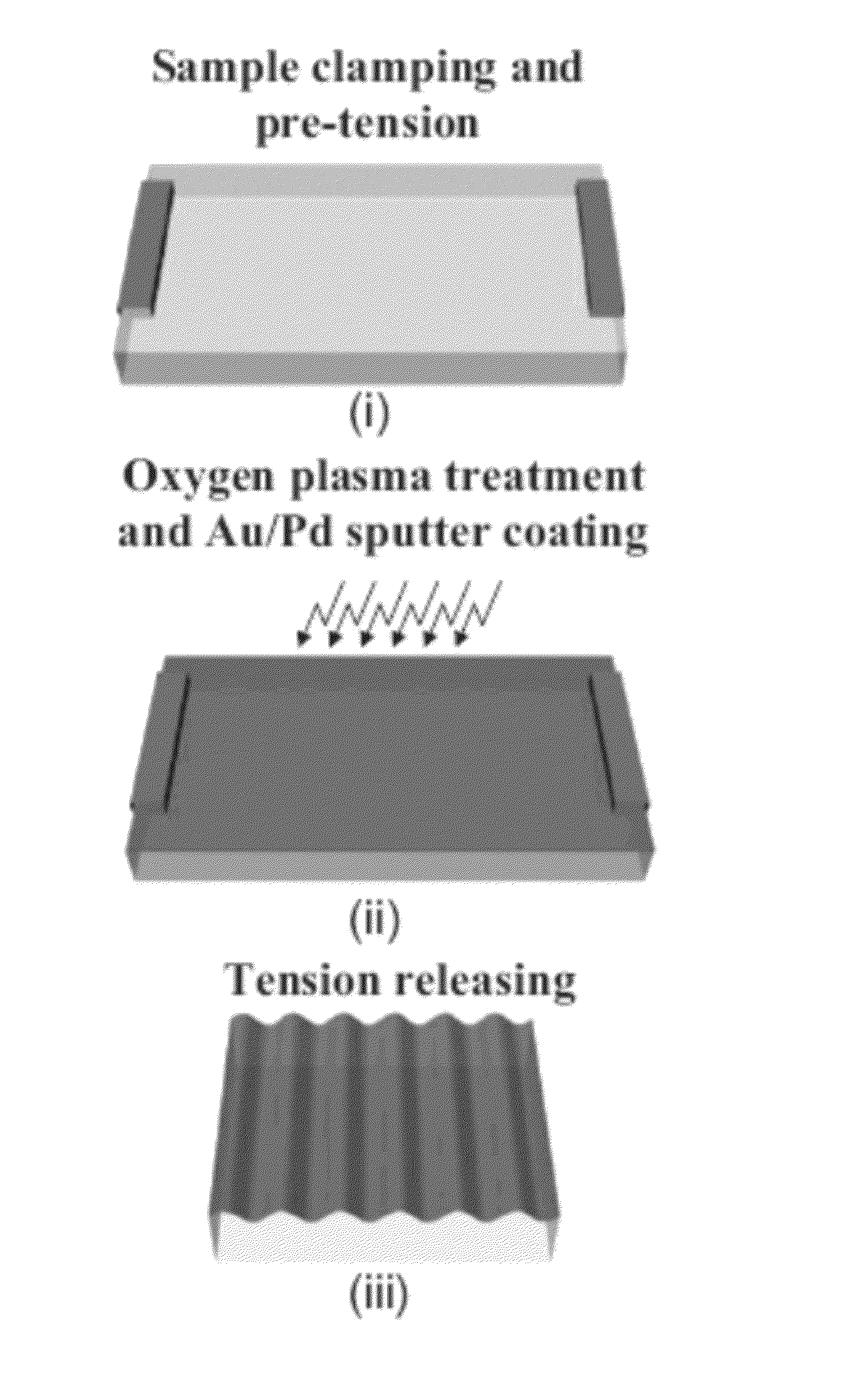
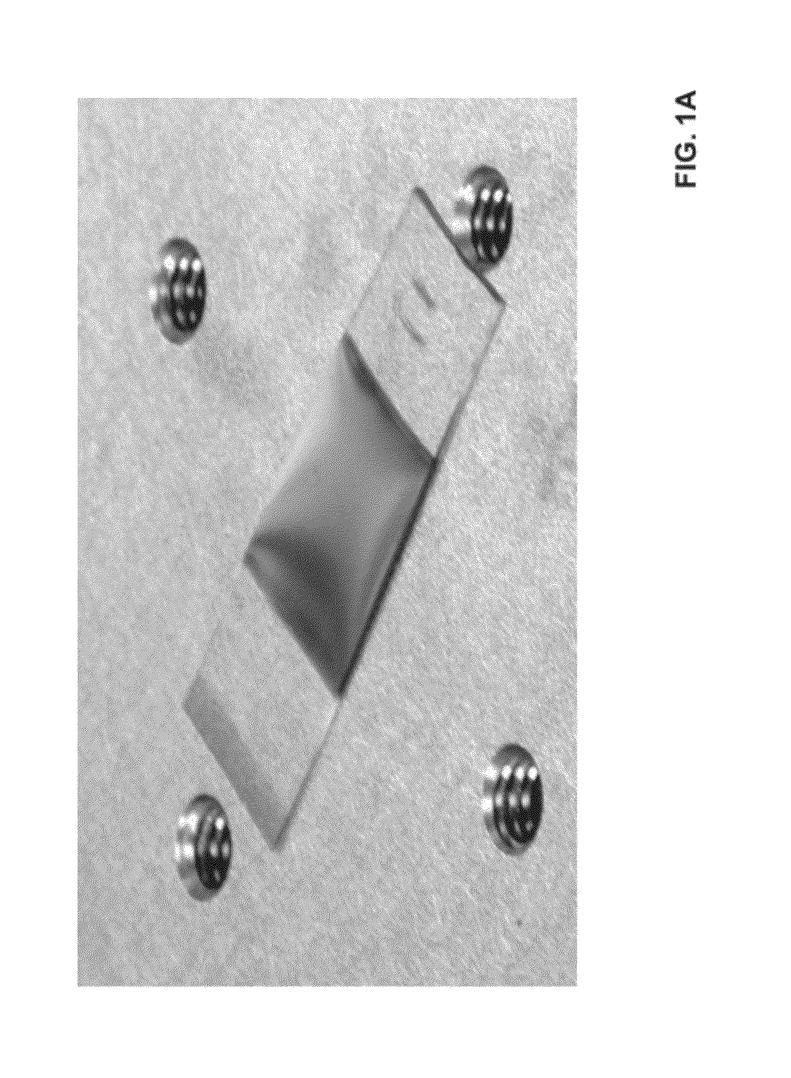
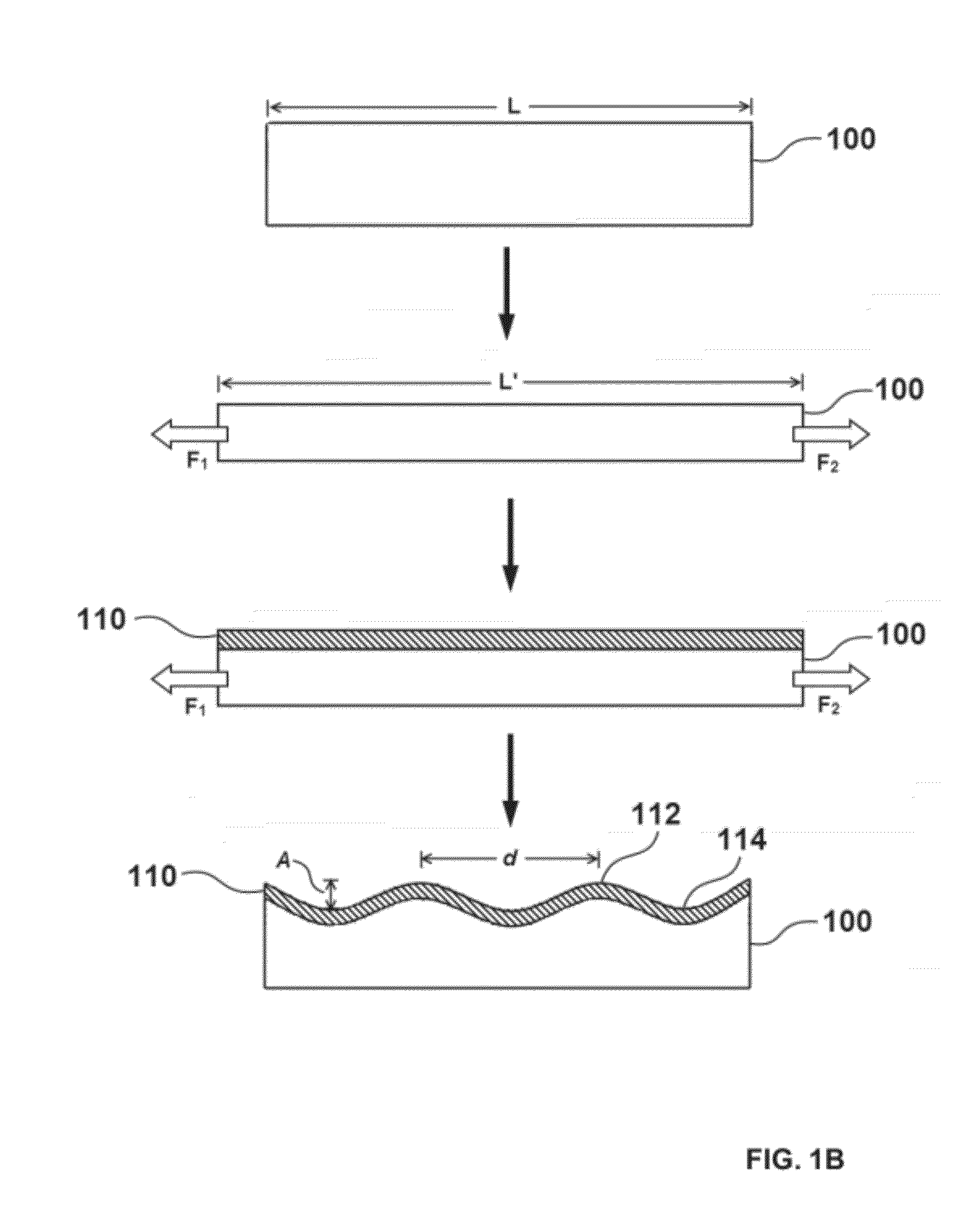
[0096]In a first example, a transparent PDMS substrate was prepared by casting a mixture of base and curing agent at the ratio of, for example, 10:1 by weight, cured and cut to desired sizes. A 1 mm-thick PDMS strip (10 mm by 40 mm) was subjected to oxygen plasma treatment (50 Watt, 1 min) and then pre-stretched by a custom made stage, at a desired amount of pre-strain. An ultra-thin Au / Pd (95% / 5%) film, about 11 nm-thick, was then sputtered onto the pre-stretched PDMS substrate. In one aspect, the relaxation of the pre-strain in the PDMS compresses the Au / Pd thin film and leads to thin films buckle in a periodic shape with buckling period in the micron range. From images of scanning electron microscope (SEM) and atomic force microscope (AFM), the buckling period d and amplitude A are measured as 1.21 mm and 0.19 mm, respectively. These values agree well with the analytical analysis (Eq. 1) if the following material parameters are used, Ef=80 GPa, Es=2 MPa, hf=11 nm, nf=0.3, ns=0.49...

example 2

Grating Performance

[0097]The periodic pattern of a buckled thin film grating can provide diffraction properties for a grating. The law of diffraction can be expressed by the grating equation:

[0098]n⁢⁢sin⁡(θm)-ni⁢sin⁡(θi)=m⁢⁢λd,(4)

[0099]where θi and θm are the angle0s of incidence and the mth diffraction order, respectively; ni is the refraction index of the incident medium; n is the refraction index of the medium where the diffracted orders propagate; λ denotes the wavelength of the incident light; and d is the period of the grating. For example, for n=ni=1 as air, θi=0, the first order diffraction spectra of visible light whose wavelength ranges from 380 nm to 760 nm would disperse at over an angular range from 22.3° to 49.5° for a grating period of 1 mm;

[0100]while the spectra would occupy a smaller range of angles from 2.1° to 4.4° for a grating of 10 mm period, making it difficult to distinguish the spectrum. Thus, to achieve a substantial diffraction over the visible light rang...


PUM

PropertyMeasurementUnit
thicknessaaaaaaaaaa
thicknessaaaaaaaaaa
temperatureaaaaaaaaaa

Abstract

Described herein are diffraction gratings and methods for the manufacture thereof. One method comprises applying a force to a substrate to strain the substrate, disposing a thin film on at least a portion of the substrate, and reducing the force applied to the substrate, thereby causing the thin film to buckle.

Description

CROSS REFERENCE TO RELATED PATENT APPLICATION[0001]This application claims priority to U.S. Provisional Application No. 61 / 435,507 filed Jan. 24, 2011, herein incorporated by reference in its entirety.STATEMENT OF GOVERNMENT SUPPORT[0002]This invention was made with United States government support under Grant CMMI0700440 awarded by the National Science Foundation. The government has certain rights in this invention.TECHNICAL FIELD[0003]The present invention relates to diffraction gratings, and specifically to methods for manufacturing diffraction gratings.BACKGROUND[0004]Diffraction gratings are utilized in a variety of technologies and can form an integral part of optical or spectral analysis tools in sensing, chemical analysis, and security applications. For example, diffraction gratings can be used as dispersive elements for spectrum analyzers or to select, tune, and expand the light spectrum of laser devices. Diffraction gratings can also be used as optical coupling elements in...

Claims


Application Information

Patent Timeline
Patent Type & Authority Patents(United States)
IPC IPC(8): G02B5/18
CPCC23C14/028C23C14/34G02B5/1847G02B26/0808
Inventor JIANG, HANQINGYU, HONGBINYU, CUNJIANGO'BRIEN, KEVINZHANG, YONG-HANG
Owner ARIZONA STATE UNIVERSITY
Why Eureka
Try Eureka