Passenger-side airbag folded body and passenger-side airbag apparatus

a passenger-side airbag and airbag technology, which is applied in the direction of pedestrian/occupant safety arrangement, vehicle components, vehicular safety arrangments, etc., can solve the problems of increased force on the object of the airbag, gas not allowed to sufficiently flow out of each vent hole, etc., to reduce the force applied, easy to unfold, and easy to unfold

Active Publication Date: 2012-05-24
JOYSON SAFETY SYST JAPAN GK
View PDF9 Cites 18 Cited by
  • Summary
  • Abstract
  • Description
  • Claims
  • Application Information

AI Technical Summary

Benefits of technology

[0020]In the passenger-side airbag folded body and passenger-side airbag apparatus according to the present invention, the vent holes, provided at the right and left sides of the airbag, are exposed at the right and left end faces of the final folded body of the airbag, respectively. Accordingly, upon inflation of the airbag in a state where an object such as an occupant is present over an instrument panel or in the immediate vicinity thereof and upon contact of the object with the airbag right after the start of the inflation of the airbag, gas quickly flows out of the airbag through each vent hole, thus reducing a force applied to the object from the airbag.
[0022]According to the third aspect, after the airbag has been formed into the vertically long primary folded body, the portion of the primary folded body located below the bag attachment ring, i.e., a lower part of the airbag, is preferably roll-folded, and the portion of the primary folded body located above the bag attachment ring, i.e., an upper part of the airbag, is preferably bellows-folded. When the airbag is folded in this manner, since bellows folding is easily unfolded, the upper part of the airbag will be quickly swollen upward and expanded toward the front of the occupant at the time of inflation of the airbag. Further, the lower part of the airbag is roll-folded and is thus expanded in such a manner that the lower part of the airbag rolls down downward at the time of inflation of the airbag, thereby allowing the lower part of the airbag to be smoothly expanded between the instrument panel and the occupant.
[0023]According to the fourth aspect, when the airbag is folded, the airbag is first formed into the spread body flatly spread out so that its longitudinal thickness is reduced. In this case, the inflator opening at the base end of the airbag is located so as to be exposed at the surface of the spread body, which is opposite to the occupant. Furthermore, each vent hole is at least partially located at the position that is below the upper end of the outer peripheral edge of the bag attachment ring surrounding the inflator opening, and that is above the lower end of the outer peripheral edge of the bag attachment ring. When the vertically long primary folded body is provided by folding the right and left end portions of the spread body along the vertical fold lines and the airbag folded body serving as the final folded body is provided by further folding the primary folded body along the lateral fold line, each vent hole is at least partially located right above the bag attachment ring. Therefore, a distance between the inflator opening and each vent hole is short, and thus gas ejected from an inflator reaches each vent hole after a lapse of a short time from the start of inflation of the airbag, so that the gas will quickly flow out of the airbag through each vent hole.

Problems solved by technology

Therefore, in the method disclosed in this patent document, even when the inflation of the airbag is started, gas is not allowed to sufficiently flow out of each vent hole until the vertical folding of the right half airbag and the left half airbag is unfolded.
Hence, even when the object is brought into contact with the airbag, gas might not be allowed to sufficiently flow out of each vent hole, and thus a force applied to the object from the airbag might be increased.

Method used


Image

  • Passenger-side airbag folded body and passenger-side airbag apparatus
  • Passenger-side airbag folded body and passenger-side airbag apparatus
  • Passenger-side airbag folded body and passenger-side airbag apparatus

Examples


Embodiment Construction

[0049]Hereinafter, exemplary embodiments of the present invention will be described with reference to the drawings.

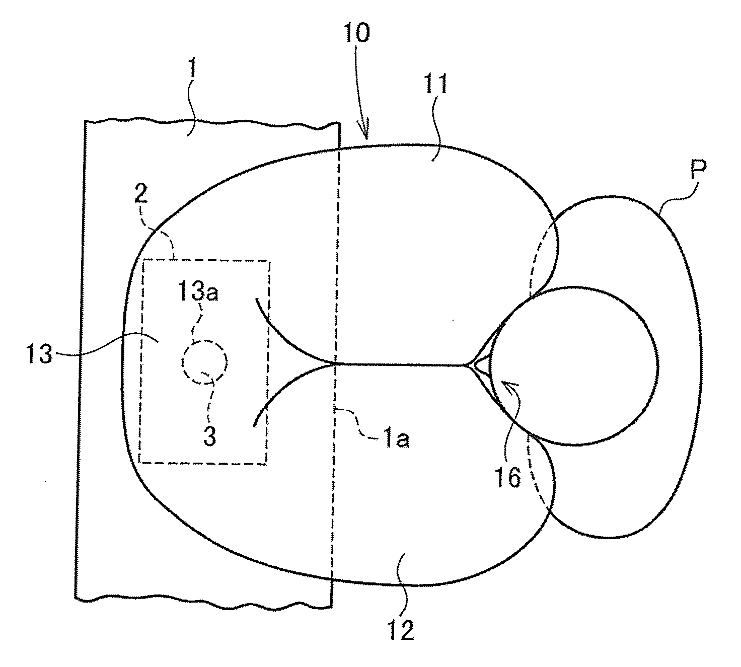
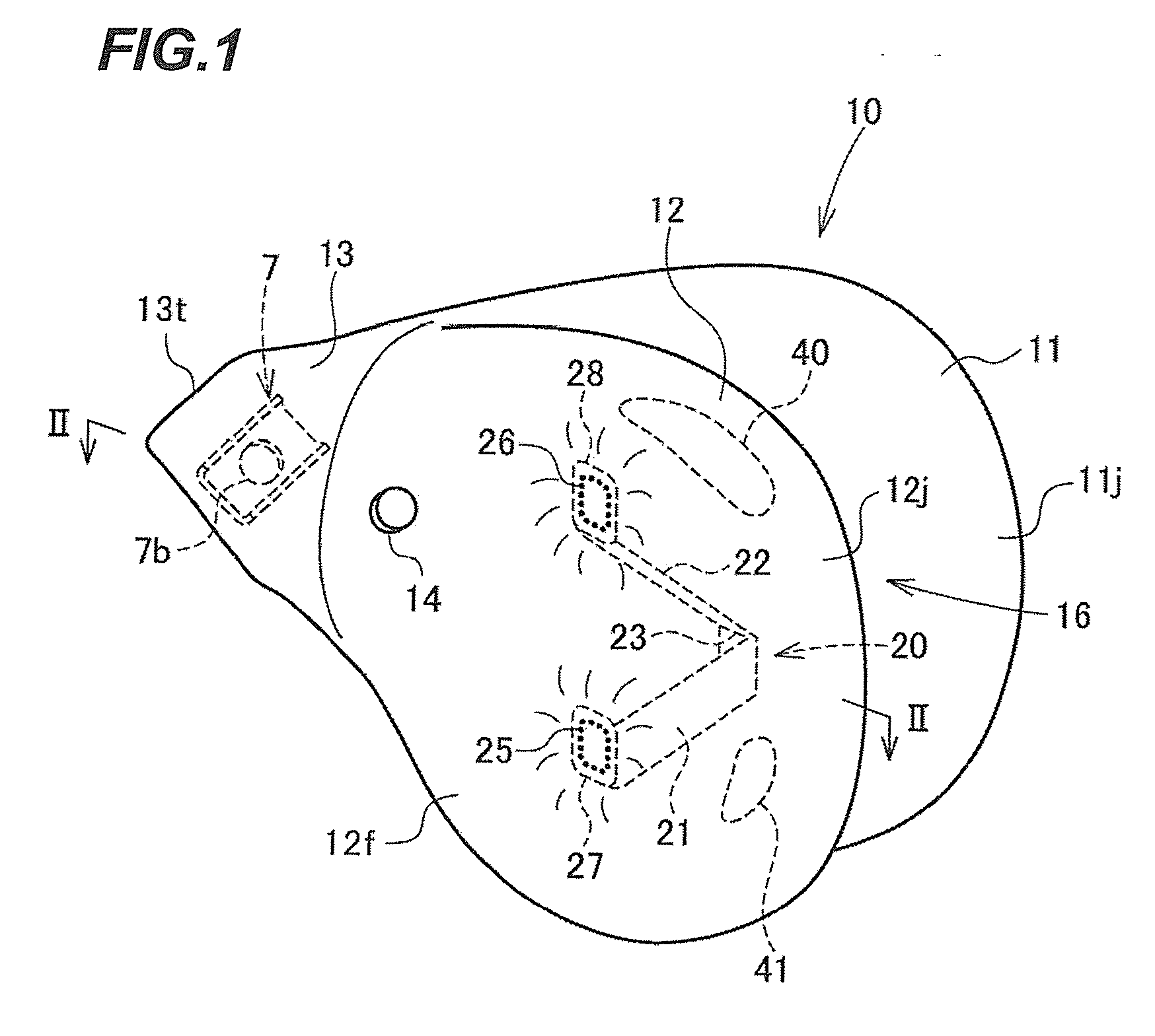
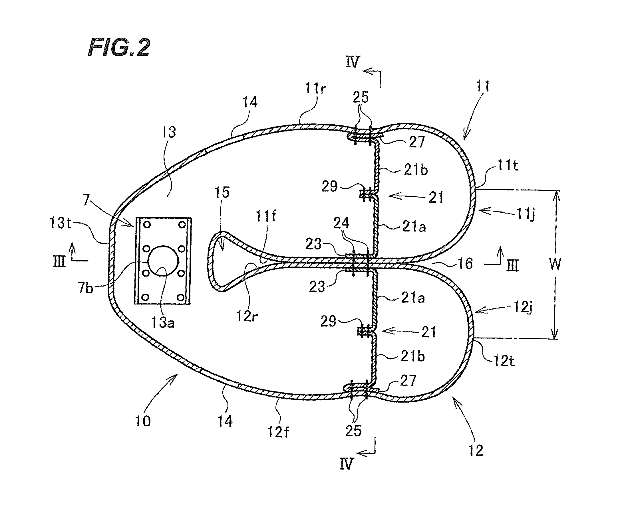
[0050]FIG. 1 is a perspective view of a passenger-side airbag (hereinafter abbreviated as an “airbag”) to be folded into an airbag folded body according to an embodiment of the present invention. FIG. 2 is a cross-sectional view taken along the line II-II of FIG. 1, FIG. 3 is a cross-sectional view taken along the line III-III of FIG. 2, and FIG. 4 is a cross-sectional view taken along the line IV-IV of FIG. 2. FIGS. 5A to 5C to FIG. 18 are explanatory diagrams illustrating a procedure of folding of the airbag. FIG. 5A is a front view illustrating a first step of folding of the airbag (as viewed from an occupant), and FIGS. 5B and 5C are cross-sectional views taken along the line B-B and the line C-C of FIG. 5A, respectively. FIG. 6 is a rear view illustrating the first step of folding the airbag (as viewed from a position opposite to the occupant). FIGS. 7A, 8A and 9A ...


PUM


Abstract

There is provided a passenger-side airbag folded body in which an inflator opening is provided at a base end of an airbag and a vent hole is provided at each of right and left side surfaces of the airbag. Right and left end parts of the airbag are folded along vertical fold lines, thereby providing a vertically long primary folded body. The primary folded body is folded along lateral fold lines, thereby providing the passenger-side airbag folded body serving as a final folded body, and the vent holes are exposed at right and left end faces of the final folded body.

Description

CROSS-REFERENCE TO RELATED APPLICATION[0001]This application claims priority under 35 U.S.C. §119 to Japanese Patent Application No. 2010-259312, filed on Nov. 19, 2010, the entire content of which is herein incorporated by reference in its entirety.BACKGROUND[0002]1. Technical Field[0003]Embodiments described herein relate to a passenger-side airbag folded body for restraining an occupant on a passenger seat at the time of vehicle collision or the like, and in particular relates to a passenger-side airbag folded body in which an inflator opening is provided at a base end thereof in an inflation direction and a vent hole is provided at each of right and left side surfaces thereof. Furthermore, the embodiments relate to an airbag apparatus including the passenger-side airbag folded body.[0004]2. Related Art[0005]As a method for folding a passenger-side airbag for restraining an occupant on a passenger seat at the time of vehicle collision or the like, the following folding method is ...

Claims


Application Information

Patent Timeline
Patent Type & Authority Applications(United States)
IPC IPC(8): B60R21/16
CPCB60R21/205B60R21/239B60R21/237
Inventor MIYATA, YASUHITO
Owner JOYSON SAFETY SYST JAPAN GK
Why Eureka
Try Eureka