Shrink fit centralizer assembly and method

a centralizer and assembly technology, applied in the direction of sealing/packing, drilling pipes, wellbore/well accessories, etc., can solve the problem that the prior art does not disclose the means of highly precise stress control, and achieve the effect of reducing stress, reducing stress, and reducing stress

Inactive Publication Date: 2005-04-21
NAT COUPLING
View PDF30 Cites 19 Cited by
  • Summary
  • Abstract
  • Description
  • Claims
  • Application Information

AI Technical Summary

Benefits of technology

[0016] Yet another objective of the another preferred embodiment of the present invention is to provide a substantially solid centralizer comprising structures therein for reducing forces applied to the stress joint or keel joint.
[0020] In a preferred embodiment, the centralizer defines and at least one preferably annular groove shaped (preferably with an axial component) to limit substantially radially directed forces from being transmitted through the rigid metal centralizer past or through the groove as a result of impact and / or forceful contact between the receptacle and the centralizer. The groove may be selectively positioned within the centralizer to reduce stress at a selected portion of the upset portion. For instance, the groove may be positioned adjacent to a first end of the upset portion to thereby reduce stress in the region of the first end of the upset portion. In another embodiment, two grooves are positioned adjacent opposite ends of the upset portion to thereby reduce stress at the opposite ends of the upset portion.
[0021] An insulative coating may be utilized on an outer surface of the centralizer to reduce corrosion, galvanic reactions, and / or dampen forces. The centralizer outer surface may comprise a curvature or substantially cylindrical surface for contact with the receptacle thereby affecting the stress applied to the upset portion in a desired manner.

Problems solved by technology

The above cited prior art does not disclose means for highly precise control of stresses and the distribution thereof in a centralized keel joint utilizing substantially solid metallic centralizers.

Method used


Image

  • Shrink fit centralizer assembly and method
  • Shrink fit centralizer assembly and method
  • Shrink fit centralizer assembly and method

Examples


Embodiment Construction

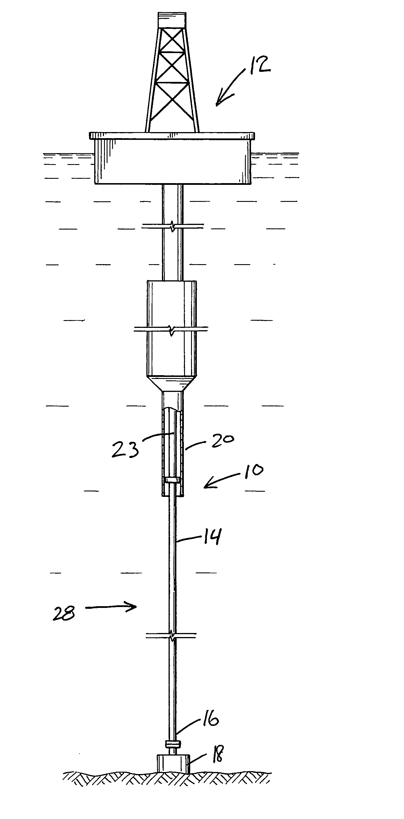
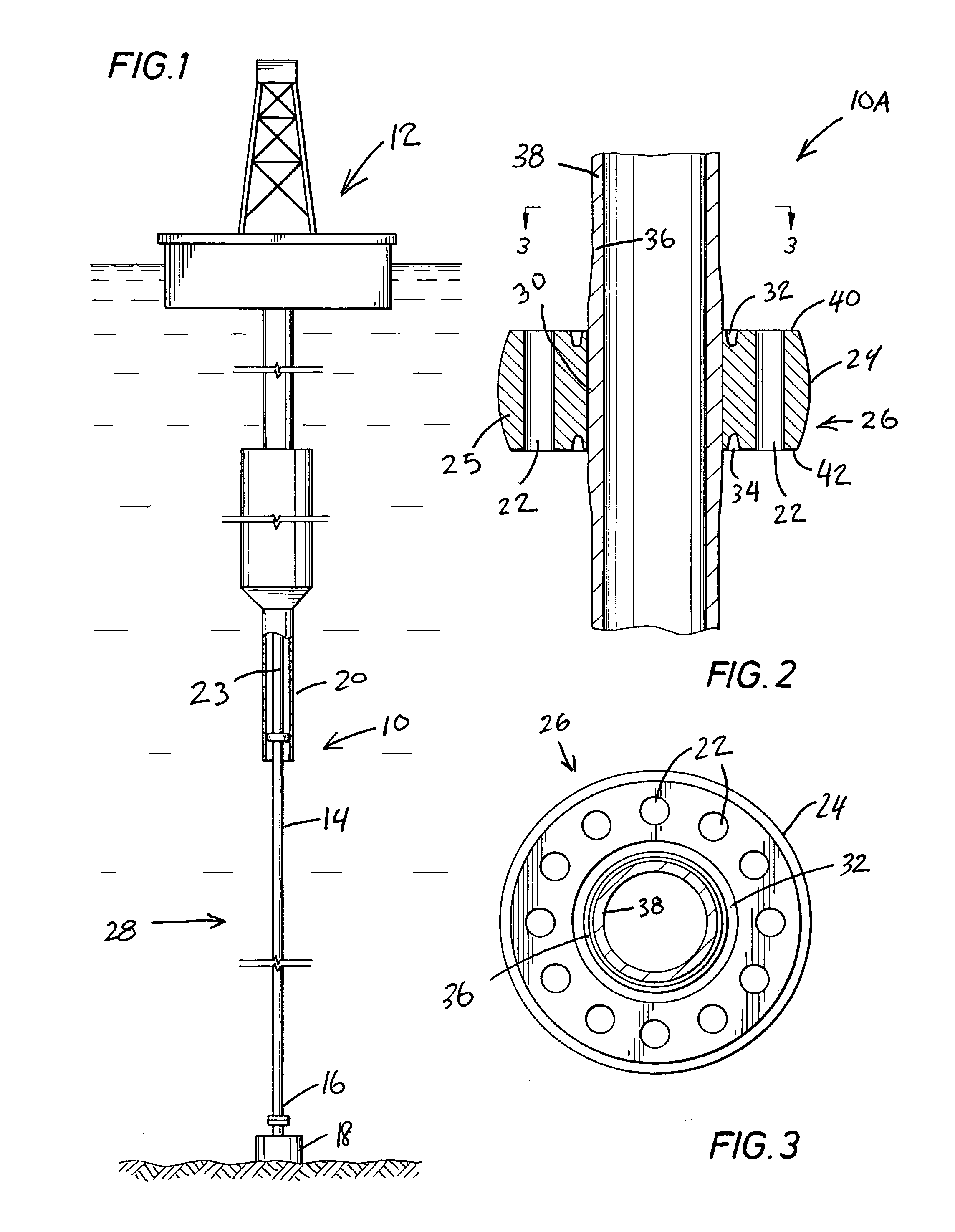
[0039] Referring now to the drawings and, more specifically, to FIG. 1, there is shown an example of non-fixed riser connection comprising a tapered keel joint with a preferably shrink fit centralizer assembly 10 for interconnection with floating platform 12 in accord with the present invention.

[0040] Floating platform 12 in FIG. 1 is shown to provide a general conception of the background of operation of tapered keel joint with shrink fit centralizer assembly 10 in accord with the present invention and is not intended to represent the great variety in construction of numerous different types of floating platforms with various different features. Floating platform 12 may comprise various types of vessels which may include without limitation, as examples only, tension leg platforms, spars, barges, ships, and the like (see for Example U.S. Pat. No. 5,887,659) referenced hereinbefore. At some point or location, depending on the particular structure of floating platform 12, a receptacl...


PUM


Abstract

A centralizer system is provided for use in a marine riser system to provide a stress joint or keel joint with a upset portion. The centralizer is preferably heat-shrink fitted to the upset portion of the keel joint. The upset portion has tapered sections on the upper and lower ends which may be of various shapes and lengths that gradually blend into the outer diameter of the pipe used as the keel joint. The centralizer may also be heat-shrink fitted to one of the tapered sections. The centralizer may or may not utilize guide sections mounted on either end thereof. In a preferred embodiment, the centralizer comprises axially extending annular grooves in surrounding relationship to the upset portion, the grooves serving to permit forces acting on the centralizer to be redirected or dissipated to thereby prevent excessive buildup on a selected region of the upset portion adjacent the radial grooves. In one embodiment, the grooves are formed annularly around the ends of the upset portion to thereby limit stresses that otherwise tend to build up on the ends of the upset portion.

Description

BACKGROUND OF THE INVENTION [0001] 1. Field of the Invention [0002] The present invention relates generally to high-load centralizer systems and, more specifically, provides a system and method which in one preferred embodiment may be utilized as keel joint subject to substantial mechanical stresses in a marine riser system. [0003] 2. Description of the Prior Art [0004] Marine risers have been utilized in the past with non-fixed connections to floating platforms and / or drill ships and / or wellheads that are maintained generally above the wellhead or in the vicinity of a plurality of wellheads. Stress joints may be utilized at the riser connections to the wellhead(s) and to the floating platform because large forces may be applied at these positions due to the relative movement between the wellhead and floating platform. The stress joint utilized at the floating platform is sometimes referred to as a keel joint because it extends through the bottom or the keel of the platform or other...

Claims


Application Information

Patent Timeline
Patent Type & Authority Applications(United States)
IPC IPC(8): E21B17/01
CPCE21B17/017
Inventor CALDWELL, CHRISTOPHER S.BAXTER, CARL F.G.ROSE, ROBERT E. JR.DYER, BRENT L.BEARD, MICHAEL
Owner NAT COUPLING
Why Eureka
Try Eureka