Composite webs and methods of manufacturing same

a technology of composite webs and webs, applied in the field of composite webs, can solve the problem of particularly fragile skin layer

Inactive Publication Date: 2008-03-20
3M INNOVATIVE PROPERTIES CO
View PDF45 Cites 19 Cited by
  • Summary
  • Abstract
  • Description
  • Claims
  • Application Information

AI Technical Summary

Benefits of technology

[0010]Solidifying the polymeric composition of the structured web before removing the structured web from the forming tool may reduce concerns regarding the internal cohesive strength of the carrier web and / or the tensile strength of the carrier web if, e.g., the carrier web includes a fibrous construction (e.g., woven, nonwoven, or knit fibers) that could be separated from the remainder of the carrier web by the forces exerted when the structured web is pulled away from the forming tool. The solidification or freezing of the polymeric composition in the structured web before removal may preferably reduce any forces exerted on the carrier web as the structured web is removed from the forming tool.
[0011]A potential advantage of the adhesive transfer and attachment processes of the present invention is that the resulting composite web may be more flexible than composite webs in which molten polymer is used to attach structures to a carrier web. The improved flexibility may be provided because the polymer of the structured webs of the present invention does not melt or infiltrate the surface of the carrier web during the attachment process.
[0012]In the case of composite webs designed to exhibit elasticity, another potential advantage of the adhesive transfer and attachment methods of the present invention may be found in more uniform elongation or extension of the carrier web. In composite webs in which molten polymer infiltrates the porous surface of the carrier web or encapsulates fibers on the surface of the carrier web, elongation of the underlying porous or fibrous carrier web may be hindered. In contrast, adhesive attachment of structured webs in accordance with the present invention to carrier webs may allow even the portions of the carrier webs that lie underneath the structures of the attached structured webs to elongate when the composite web is stretched.
[0013]Another potential advantage of the adhesive transfer and attachment methods of the present invention is that the carrier web may retain its strength after attachment of the structured web. In composite webs that rely on molten polymer infiltrating a porous carrier web or encapsulating fibers of a fibrous carrier web for attachment of structures formed by the molten polymer, the tensile strength of the underlying carrier web may be reduced at the edges of the polymer structures fused to the carrier web.
[0014]Still another potential advantage of the methods of the present invention is the ability to attach structures to the carrier web, where the structures have a selected shape that is defined by the depressions in the forming tool used to deliver the structures to the carrier web (as a part of the structured web). Control over the shape of the structures of the structured web may provide improved control over the mechanical properties associated with those structures (e.g., elasticity, strength, size, etc.).
[0015]Yet another potential advantage of the methods of the present invention is the ability to provide the structures of the structured web in a selected arrangement on the surface of the carrier web. That selected arrangement is defined by the corresponding arrangement of the depressions on the forming tool and is maintained during removal and attachment of the structures and associated skin layer because the removal is accomplished directly from the forming tool to the carrier web (while the structured web is preferably maintained in a relaxed state).

Problems solved by technology

As a result, the skin layer may be particularly fragile.

Method used


Image

  • Composite webs and methods of manufacturing same
  • Composite webs and methods of manufacturing same
  • Composite webs and methods of manufacturing same

Examples


example

[0108]The following non-limiting example is provided only to illustrate one method of manufacturing a composite web in accordance with some principles of the present invention.

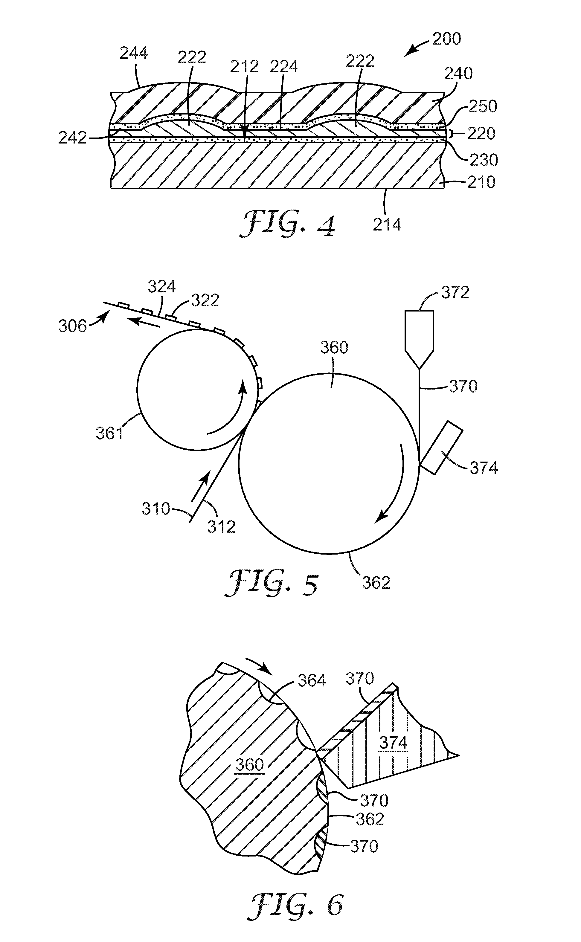
[0109]A composite web was produced using a system similar to that shown in FIG. 5. A 75 mm diameter single screw extruder was used to deliver a molten polymer consisting of a blend of 70% by weight styrene-ethylenebutylene-styrene block copolymer (KRATON G1657), 30% by weight metallocene-catalyzed polyethylene (Engage 8452), and 2 parts per hundred TiO2 masterbatch (Clariant), at a melt temperature of approximately 235 degrees C to a neck tube.

[0110]The neck tube was connected to a die that delivered the molten polymer to the exterior surface of a steel forming roll having a circumference of approximately 185 cm. The die was designed to deliver the molten polymer in two separate stripes so as to deposit the molten polymer onto the portions of the forming roll bearing depressions, as described below. At the bas...


PUM

PropertyMeasurementUnit
thicknessaaaaaaaaaa
thicknessaaaaaaaaaa
thicknessaaaaaaaaaa

Abstract

Composite webs having a structured web attached to a carrier web and methods of manufacturing the composite webs are disclosed. The structured web may include a plurality of structures that protrude from the structured web. The methods may involve delivering a molten polymeric composition onto the outer surface of a forming tool that includes a plurality of depressions formed in the outer surface. The molten polymer enters depressions in the outer surface of the forming tool and is solidified therein such that a plurality of structures are formed in the shape of the depressions. A skin layer of the polymeric composition may extend between the depressions, such that the structured web formed on the forming tool includes a skin layer connecting the structures. The structured web is removed from the forming tool after solidification of the polymeric composition by adhering the structured web to a carrier web using adhesive located between the carrier web and structured web.

Description

TECHNICAL FIELD[0001]The present invention relates to composite webs and methods of manufacturing the composite webs. The composite webs include a carrier web with a structured web that includes a plurality of polymeric structures attached to at least one major surface of the carrier web.BACKGROUND OF THE INVENTION[0002]The manufacture of composite webs that require the attachment of reinforcing and / or elastic components to an underlying substrate is the subject of many different approaches. Although reinforcement may be provided over the entire substrate, such approaches can add unnecessary cost and / or weight to the composite web. Such constructions may also increase stiffness over the entire surface of the composite web.[0003]While a variety of approaches to providing discrete polymeric structures on substrates are disclosed in, e.g., U.S. Patent Application Publication No. US 2003 / 0085485 A1, filed 5 Nov. 2001 and titled SYSTEMS AND METHODS FOR COMPOSITE WEBS WITH STRUCTURED DISC...

Claims


Application Information

Patent Timeline
Patent Type & Authority Applications(United States)
IPC IPC(8): B32B37/00D04H13/00B32B27/12B32B38/04D04H1/00B29C65/00D04H3/00
CPCB32B37/0053B32B37/1292B32B37/153Y10T156/1737B32B2309/02B32B2555/02B32B2307/51Y10T428/249982Y10T442/60Y10T442/601Y10T442/674
Inventor ALBERG, RANDALL L.BECKER, DENNIS L.JACKSON, BYRON M.MCDONALD, DANIEL S.WOOD, LEIGH E.
Owner 3M INNOVATIVE PROPERTIES CO
Why Eureka
Try Eureka