
Automobile bijump lamp, steering lamp automatic switching device

A technology of double jumping lights and turn signals, applied in vehicle parts, optical signals, signaling devices, etc., can solve problems such as easy traffic accidents and troublesome operation.

Inactive Publication Date: 2005-08-10
孙月祥
View PDF0 Cites 2 Cited by
  • Summary
  • Abstract
  • Description
  • Claims
  • Application Information

AI Technical Summary

Problems solved by technology

When the turn is over, the double-jump light switch must be turned on again to restore the four turn lights to flash at the same time to achieve the effect of double-jump lights. This operation is very troublesome, and it is easy to cause traffic accidents

Method used


Image

  • Automobile bijump lamp, steering lamp automatic switching device
  • Automobile bijump lamp, steering lamp automatic switching device

Examples


Embodiment Construction

[0008] The present invention will be further described below in conjunction with the accompanying drawings.

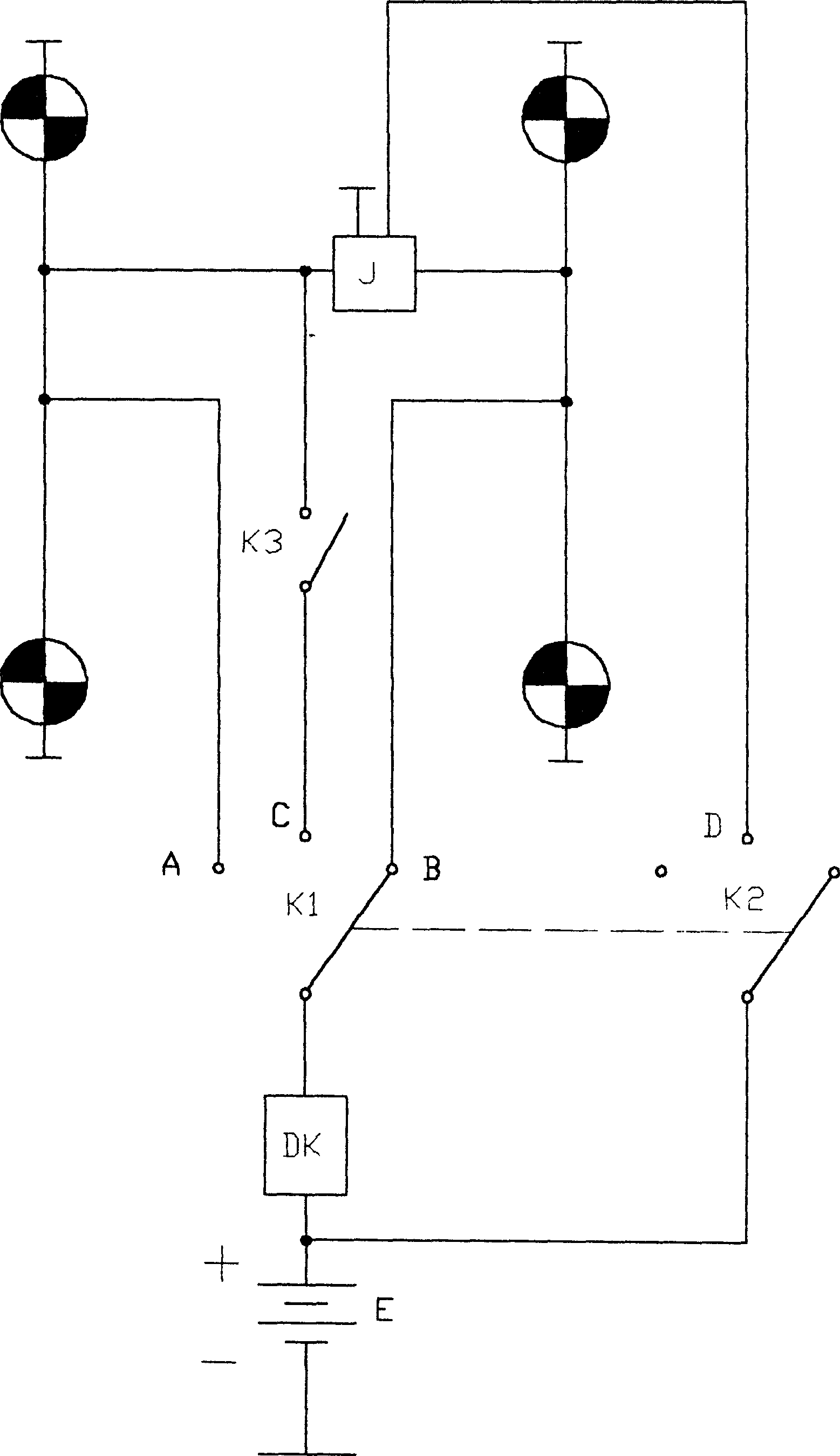
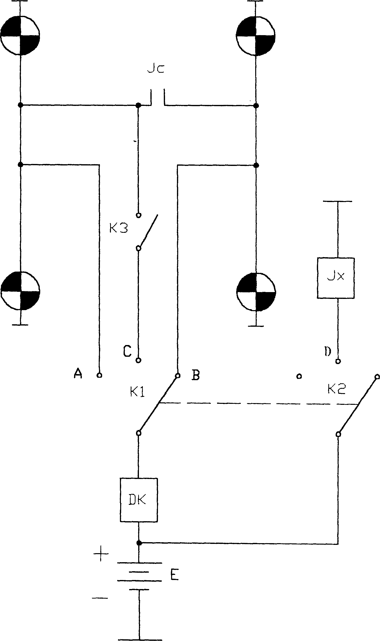
[0009] figure 1 It is the circuit schematic diagram of the double-jump lamp and the automatic converter of the turn signal of the car. It includes front and rear, left and right turn signals, interrupter Dk, power supply E for lighting and control, and double-jump light switch K3. K2 is connected between the power supply E and the interrupter Dk; the left and right positions of K1 are respectively connected with the left and right turn signals, and the middle position is connected with a double-jump light switch K3; there is a conversion control connected between the left and right turn signals Device J, the other end of the double-jump light switch K3 is connected to either side of the left turn signal or the right turn signal, and the K2 of the two-pole three-position switch is connected to the conversion controller J.

[0010] figure 2 It is a schematic circuit ...


PUM


Abstract

An automatic switching device for the dual-state lamps and direction signal lamps of car is composed of 4 direction signal lamps, power supply for lighting and control and connected with at least two double-pole three-throw switches, a ticker, a switch for dual-state lamps, and switching controller.

Description

technical field [0001] The invention belongs to the technical field of circuits, in particular to the technology of automotive lighting circuits. Background technique [0002] In the lighting design of the car, the double-jump lights are designed for non-special vehicles to perform special tasks and need to pass through first. When turning, it is necessary to indicate that the left or right turn signal flashes, the double-jump light switch must be turned off, and the turn signal switch must be turned on, so that the turn signal can flash on one side. When turning to the end, it is necessary to turn on the double-jump light switch to restore four turn signal lights to flash simultaneously to achieve the effect of double-jump lights. This operation is very troublesome and easily causes traffic accidents. Contents of the invention [0003] The purpose of the present invention is to overcome the shortcoming existing in the above-m...

Claims


Application Information

Patent Timeline
IPC IPC(8): B60Q1/26
Inventor 孙月祥
Owner 孙月祥
Learn More