Whirlwind barrel for dust collector

A cyclone and vacuum cleaner technology, applied in suction filters and other directions, can solve the problems of dust escape, reduce the dust removal efficiency of the cyclone cylinder, and achieve the effect of improving the dust removal efficiency.

Active Publication Date: 2005-08-17
ECOVACS ROBOTICS (SUZHOU ) CO LTD
View PDF0 Cites 23 Cited by
  • Summary
  • Abstract
  • Description
  • Claims
  • Application Information

AI Technical Summary

Problems solved by technology

However, since part of the airflow entering the dust separation chamber will spiral upwards to the top of the dust separation chamber, and then rotate downwards near the draft tube, when this part of the airflow moves to the outside of the air intake mesh cover, it is easy to enter directly. Mesh holes, resulting in dust escape, reducing the dust removal efficiency of the cyclone cylinder

Method used


Image

  • Whirlwind barrel for dust collector
  • Whirlwind barrel for dust collector
  • Whirlwind barrel for dust collector

Examples


Embodiment Construction

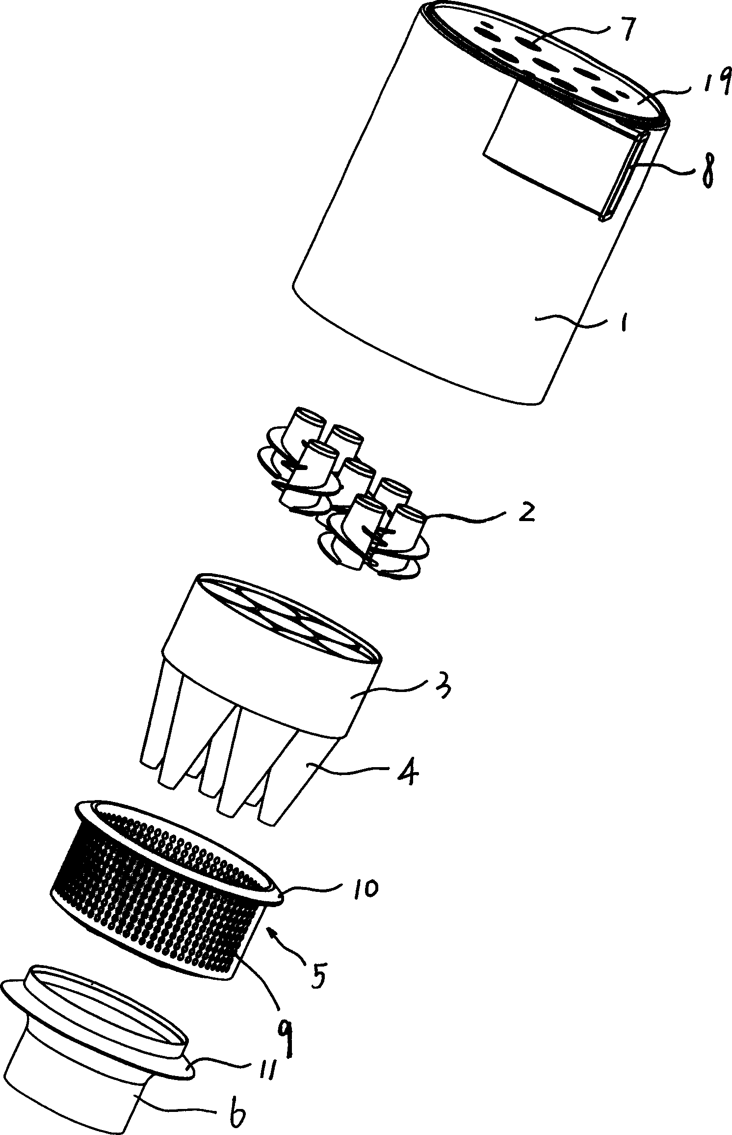
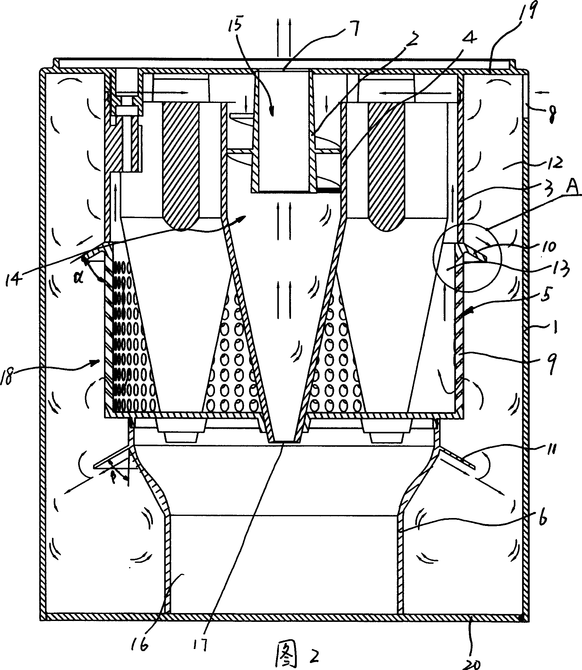
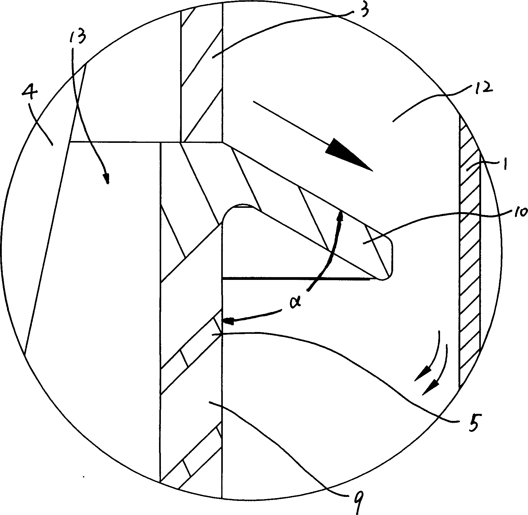
[0010] See attached figure 1 - Accompanying drawing 3, a cyclone cylinder of a vacuum cleaner, comprising a cylinder 1 having an air inlet 8, and a guide tube 18 coaxially arranged in the cylinder 1, the guide tube 18 and the A dust separation chamber 12 is formed between the cylinders 1. The top of the dust separation chamber 12 has a top cover 19 arranged between the cylinder 1 and the draft tube 18. The bottom of the dust separation chamber 12 has a top cover arranged on the cylinder 1. The bottom cover 20 between the guide pipe 18 and the dust separation chamber 12 communicate with the air inlet 8 . The draft tube 18 includes the upper draft tube body 3, the lower inner dust tube 6, and the air intake mesh cover 5 between the draft tube body 3 and the inner dust tube 6. In the present invention In the embodiments shown in the accompanying drawings, the draft duct body 3, the inner dust cylinder 6, and the air intake mesh cover 5 are three independent parts, wherein the in...


PUM


Abstract

The cyclonic barrel for dust collector includes barrel body with air inlet and guide tube inside the barrel body, and one dust separating chamber is formed between the guide tube and the barrel body and is provided with top cover and bottom cover. The guide tube includes inlet meshed cover, and upper skirt over the inlet meshed cover and with outer edge radially expanded to cover the periphery of the inlet meshed cover. Under the action of the upper skirt, the inside cyclonic airflow moves towards the inner wall of the barrel body to converge with the outside cyclonic airflow and the converted airflow further moves downwards to reach the aim of separating dust.

Description

technical field [0001] The invention relates to a cyclone cylinder body of a vacuum cleaner Background technique [0002] The cyclone barrel of the existing vacuum cleaner includes a barrel, a guide tube arranged in the barrel, a dust separation chamber is formed between the guide tube and the barrel, and the guide tube includes an upper body, a middle air intake mesh cover and In the lower inner dust cylinder, the air with dust enters the bottom of the dust separation chamber from the air inlet on the cylinder. in the lumen. However, since part of the airflow entering the dust separation chamber will spiral upwards to the top of the dust separation chamber, and then rotate downwards near the draft tube, when this part of the airflow moves to the outside of the air intake mesh cover, it is easy to enter directly. Mesh holes, resulting in dust escape, reducing the dust removal efficiency of the cyclone cylinder. Contents o...

Claims


Application Information

Patent Timeline
Patent Type & Authority Applications(China)
IPC IPC(8): A47L9/16
Inventor 钱东奇
Owner ECOVACS ROBOTICS (SUZHOU ) CO LTD
Why Eureka
Try Eureka