Tableware washing machine
A dishwashing machine and cleaning agent technology, applied in dishwashing machine/washing machine, dishwashing machine/rinsing washing machine parts, cleaning equipment, etc., can solve the problems such as the inability to greatly improve the cleaning performance and the inability to ensure the concentration.
- Summary
- Abstract
- Description
- Claims
- Application Information
AI Technical Summary
Problems solved by technology
Method used
Image
Examples
Embodiment 1
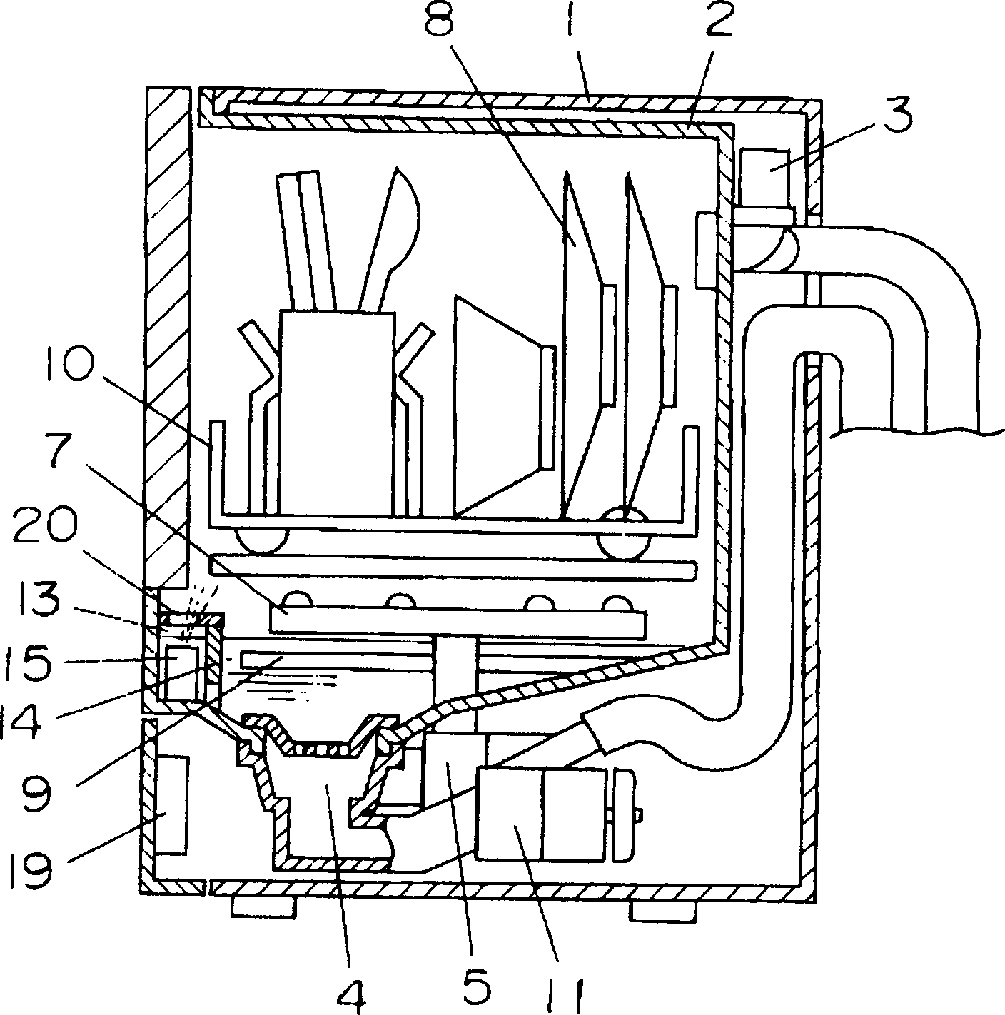
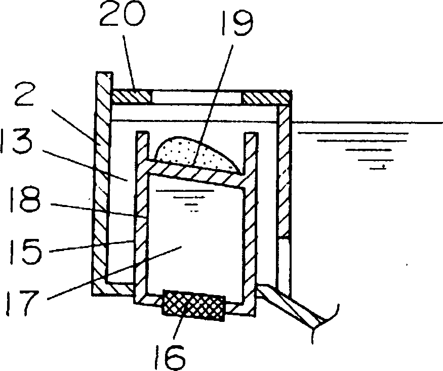
[0017] figure 1 It is a longitudinal sectional view of the dishwasher in Embodiment 1 of the present invention, figure 2 It is an enlarged vertical cross-sectional view of the main structure of the atomization generating device. like figure 1 As shown in , the cleaning agent solution forming unit 13 is arranged near one side of the front of the cleaning tank 2 , and a partition 14 is separated from the cleaning tank 2 . A notch is provided on the dividing plate 14 and communicates with the inside of the cleaning tank 2 . The cleaning solution forming unit 13 is provided with an atomization generator 15 for atomizing the cleaning solution formed in the cleaning solution forming unit 13 . Structure of atomization generating device 15 figure 2 As shown in , an ultrasonic oscillator (an oscillator for atomization) 16 is provided on the bottom surface, and a container 18 in which a liquid 17 is sealed is provided above the vibrating surface of the ultrasonic oscillator 16 ....
Embodiment 2
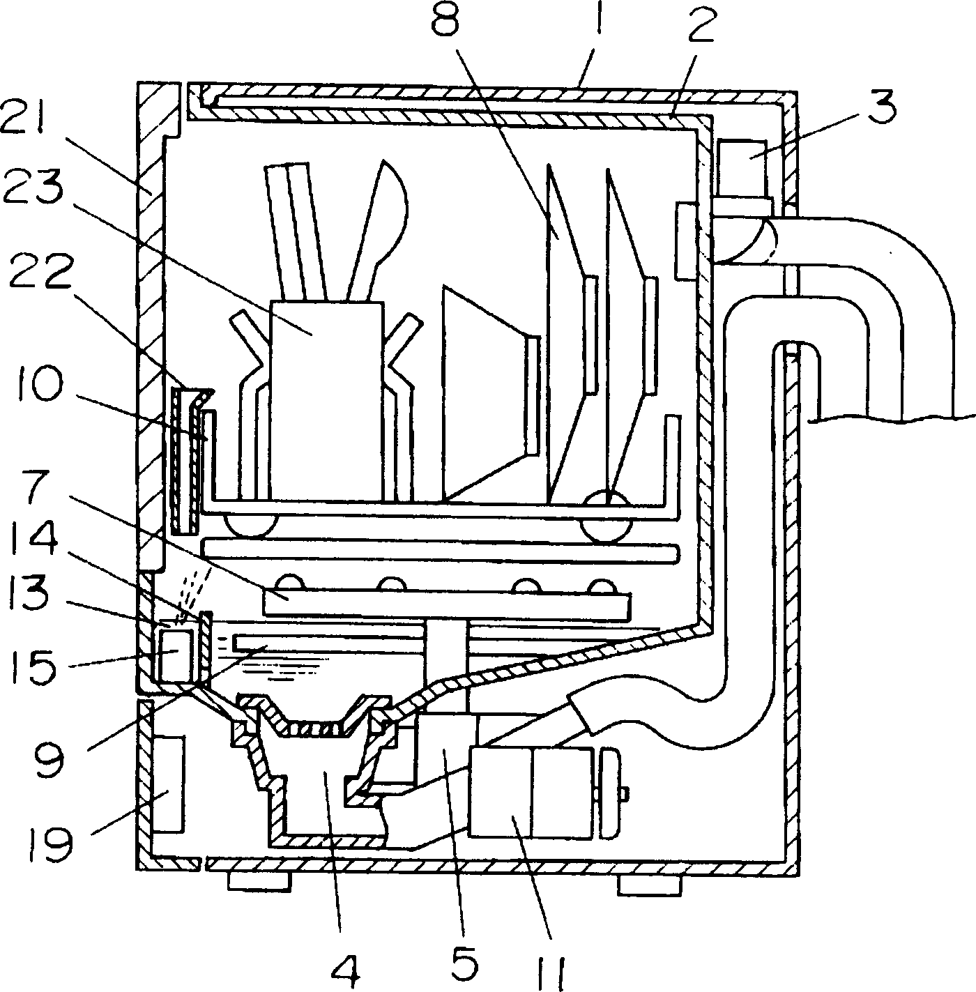
[0026] image 3 It is a vertical cross-sectional view of the dishwasher in Example 2 of the present invention. image 3 Among them, the door 21 is used to open / close the opening of the washing tank 2, and a central axis of rotation substantially parallel to one side below the opening of the washing tank 2 is provided on it. In the state where the machine door 21 is opened, the cutlery basket 10 containing the objects to be cleaned 8 can move between the upper surface of the machine door 21 and the cleaning tank 2 . On the front end side of the dish basket 10, a cleaning agent input part 22 is provided, and is in a position corresponding to the cleaning agent solution forming unit 13 provided at the front end of the washing tank 2. The other structures are the same as those of the above-mentioned Embodiment 1, so detailed description thereof will be omitted.
[0027] The operation and its effect in the dishwasher having the above structure will be described below. First, a p...
Embodiment 3
[0031] Figure 4 It is a longitudinal sectional view of the dishwasher in Example 3 of the present invention. exist Figure 4 Among them, the cleaning agent input part 24 integrated with the machine door 21 is arranged on the inner surface side of the machine door 21, that is, on the side of the cleaning tank 2, and is facing the cleaning solution forming unit 13 arranged at the front end of the cleaning tank 2. position. Since the other configurations are the same as those in the above-mentioned embodiment 2, detailed description thereof will be omitted.
[0032] The operation and its effect in the dishwasher having the above structure will be described below. First, add a prescribed amount of cleaning agent to the cleaning agent input part 24, and close the machine door 21; 13; Afterwards, by performing the same operation as in Example 1, the high-concentration cleaning agent solution can be scattered in the cleaning tank 2, and these high-concentration cleaning agent so...
PUM
 Abstract
Description
Claims
Application Information
 - R&D
- Intellectual Property
- Life Sciences
- Materials
- Tech Scout
- Unparalleled Data Quality
- Higher Quality Content
- 60% Fewer Hallucinations
Browse by: Latest US Patents, China's latest patents, Technical Efficacy Thesaurus, Application Domain, Technology Topic, Popular Technical Reports.
© 2025 PatSnap. All rights reserved.Legal|Privacy policy|Modern Slavery Act Transparency Statement|Sitemap|About US| Contact US: help@patsnap.com


