Method and apparatus to control a focal length of a curved reflector in real time

a technology of curved reflector and control device, which is applied in the direction of lighting and heating equipment, instruments, optical elements, etc., can solve the problems of reducing affecting the efficiency of lighting, and affecting the effect of lighting, so as to achieve the effect of more energy

Active Publication Date: 2012-08-16
TOYOTA JIDOSHA KK
View PDF42 Cites 16 Cited by
  • Summary
  • Abstract
  • Description
  • Claims
  • Application Information

AI Technical Summary

Benefits of technology

[0007]Each of the curved reflectors can include, for example, a curved body, a stand, and / or an actuation unit. The curved body can reflect the light from the light source to concentrate it onto the tower. When the light source moves, the curved body can pivot about the stand to track the light source. Furthermore, the actuation unit can be activated to adjust a focal length of a focal point of the curved body to ensure that the reflected light is concentrated at the tower instead of in front of or behind the tower. This is beneficial because the tower receives more light when the reflected light is concentrated at the tower. When the tower receives more light, it produces more energy.

Problems solved by technology

However, the conventional curved reflector usually only pivots in response to the movement of the light source.
This is problematic because as the light source moves, the location of the focal point may change.
However, the movement of the light source usually changes the focal length.
This is undesirable because the focused energy is wasted if it is focused closer or further away than the tower.

Method used


Image

  • Method and apparatus to control a focal length of a curved reflector in real time
  • Method and apparatus to control a focal length of a curved reflector in real time
  • Method and apparatus to control a focal length of a curved reflector in real time

Examples


Embodiment Construction

[0018]Apparatus, systems and methods that implement the embodiments of the various features of the present invention will now be described with reference to the drawings. The drawings and the associated descriptions are provided to illustrate some embodiments of the present invention and not to limit the scope of the present invention. Throughout the drawings, reference numbers are re-used to indicate correspondence between referenced elements.

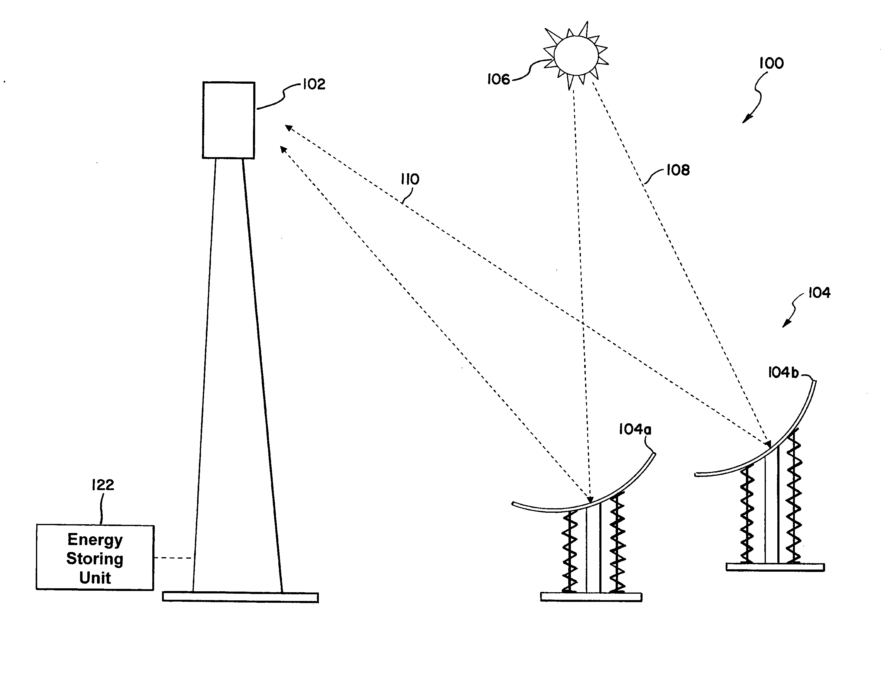
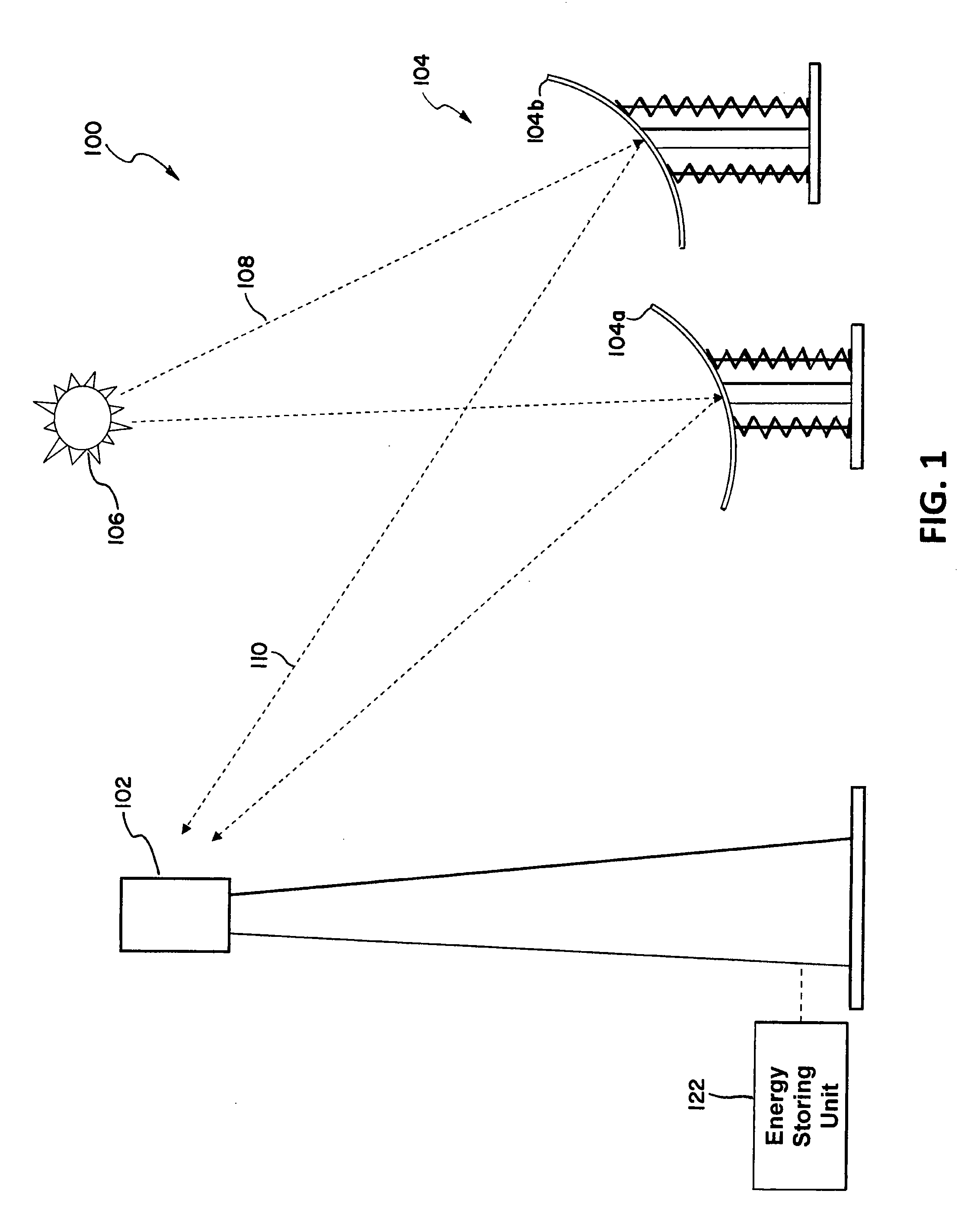
[0019]In one embodiment, the present invention can be directed to an energy generation system 100 as shown in FIG. 1. The energy generation system 100 can include a tower 102, a plurality of curved reflectors 104, and / or an energy storing unit 122. For example, as seen in FIG. 1, the curved reflectors 104 can include curved reflectors 104a and 104b. The energy generation system 100 can harness energy from a light source such as a sun 106 and store the harnessed energy in the energy storing unit 122.

[0020]For example, light 108 from the sun 106...


PUM


Abstract

The present invention relates to a method and apparatus to control a focal length of a curved reflector in real time. An energy generation system includes curved reflectors, a tower, and an energy storing unit connected to the tower. The curved reflectors reflect and concentrate light from a light source onto the tower. The tower converts the received light into usable energy which is stored in the energy storing unit. Each of the curved reflectors can include a curved body, a stand, and/or an actuation unit. The curved body reflects the light from the light source to concentrate it onto the tower. When the light source moves, the curved body pivots about the stand to track the light source. The actuation unit is activated to adjust a focal length of the focal point of the curved body to ensure that the reflected light is concentrated at the tower.

Description

BACKGROUND[0001]1. Field[0002]The present invention relates to a method and apparatus to control a focal length of a curved reflector in real time.[0003]2. Description of the Related Art[0004]A conventional heliostat can be a conventional curved reflector that is pivoted as the sun moves to focus light from a light source, such as the sun onto a target such as a tower. The energy from the conventional heliostat is then collected at the tower and converted into usable energy which is stored for later use. However, the conventional curved reflector usually only pivots in response to the movement of the light source. This is problematic because as the light source moves, the location of the focal point may change. That is, the focal point is usually located at a focal length away from the curved reflector. However, the movement of the light source usually changes the focal length. Thus, the light that is reflected from the conventional curved reflector may be focused at an area that is...

Claims


Application Information

Patent Timeline
Patent Type & Authority Applications(United States)
IPC IPC(8): F24J2/38G02B7/185F24S23/71F24S50/20
CPCG02B5/10G02B7/183F24J2/38F24J2/125Y02E10/42F24S23/715F24S50/20Y02E10/40
Inventor GANDHI, UMESH N.
Owner TOYOTA JIDOSHA KK
Why Eureka
Try Eureka