Centrifugal force harnessing system and power generation method

a technology of centrifugal force and harnessing system, which is applied in the direction of couplings, rotary clutches, fluid couplings, etc., can solve the problems of no energy could be extracted from the system without reducing the angular momentum of the mass, and all previous attempts to harness this effect have failed, so as to achieve the effect of generating more energy and balancing the system during operation

Inactive Publication Date: 2013-09-26
HEISS JOHN CHARLES
View PDF2 Cites 2 Cited by
  • Summary
  • Abstract
  • Description
  • Claims
  • Application Information

AI Technical Summary

Benefits of technology

[0007]The present invention relates to the development of a system that exploits the characteristics of water or other liquids when subjected to the centrifugal force induced by rotation. Under these conditions, water may be pumped vertically by a pump situated inwardly on a rotating platform. By design, the pump is positioned so that during operation, it is constantly immersed in water. Accordingly, the energy required to elevate the water is negligibly affected by the rotation of the platform as the pump does not have to pull the water inwardly against the influence of centrifugal force. Furthermore, the discharge point of the water being pumped upwardly is located at a radius external to the position of the pump whereby the acceleration of the water moving outwardly assists in the circulatory action. As the water reaches an upper section of horizontal pipe, it accelerates outwardly due to centrifugal force as it passes through a hydro electric turbine installed within the outer portion of pipe. At this outward location, the water exerts pressure enhanced by the effects of rotation on the turbine and therefore generates more energy than is required to elevate it vertically by the inwardly positioned pump. After passing through the turbine and an air gap, the water is returned to the pump by gravity. By establishing and maintaining a constant rotational velocity of the entire assembly to achieve the aforementioned conditions, the circulating liquid mass remains constant at all times along the radius of the rotating platform. The mass of water rotating at a higher velocity on the outer radius of the system is pulled down and inwardly by gravity and offsets the mass of the slower moving water circulating outwardly. As a result, the system does not require additional energy to maintain rotational velocity and thus has the potential to produce energy in excess of operational requirements. A more detailed description of the particular embodiments of the invention is illustrated in the accompanying drawings. It should be noted that opposing pairs of components are installed as illustrated to ensure the system is balanced during operation. In addition, a plurality of opposing pairs may be mounted on a single, rotating platform.

Problems solved by technology

All previous attempts to harness this effect have failed due to the laws expressed in the conservation of angular momentum theorem.
As a result, under previous models, no energy could be extracted from the system without reducing the angular momentum of the mass.

Method used


Image

  • Centrifugal force harnessing system and power generation method
  • Centrifugal force harnessing system and power generation method
  • Centrifugal force harnessing system and power generation method

Examples


Embodiment Construction

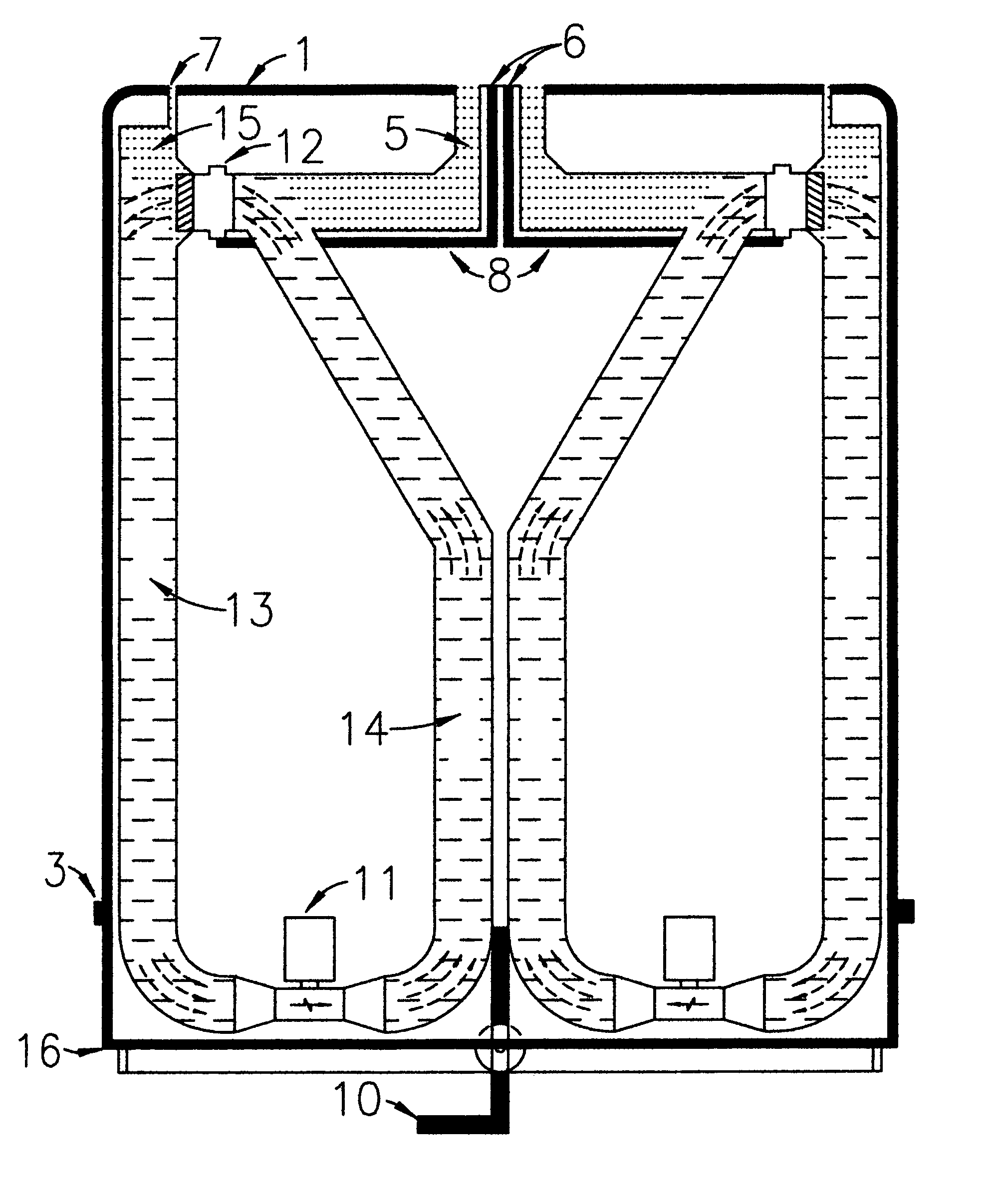
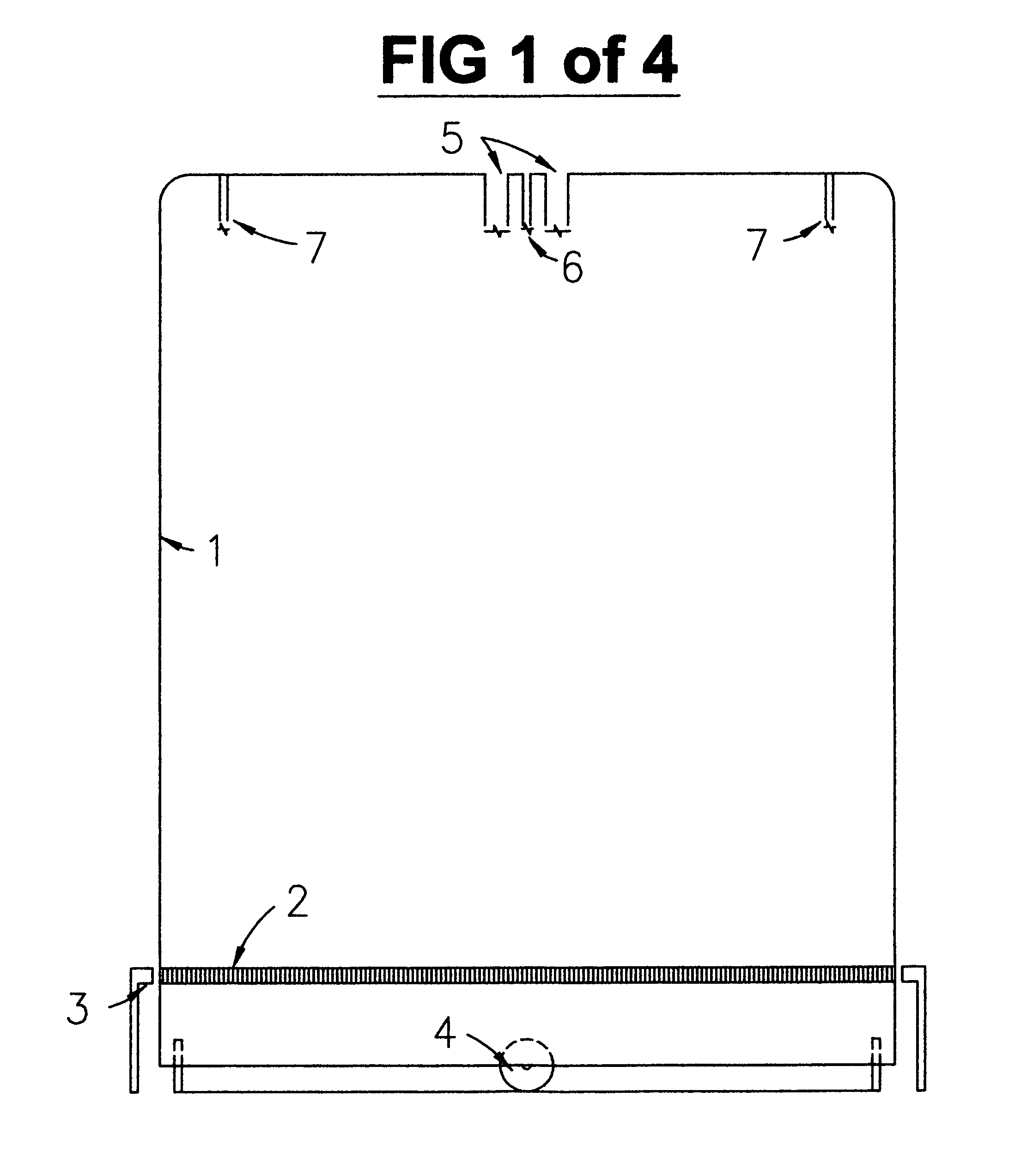
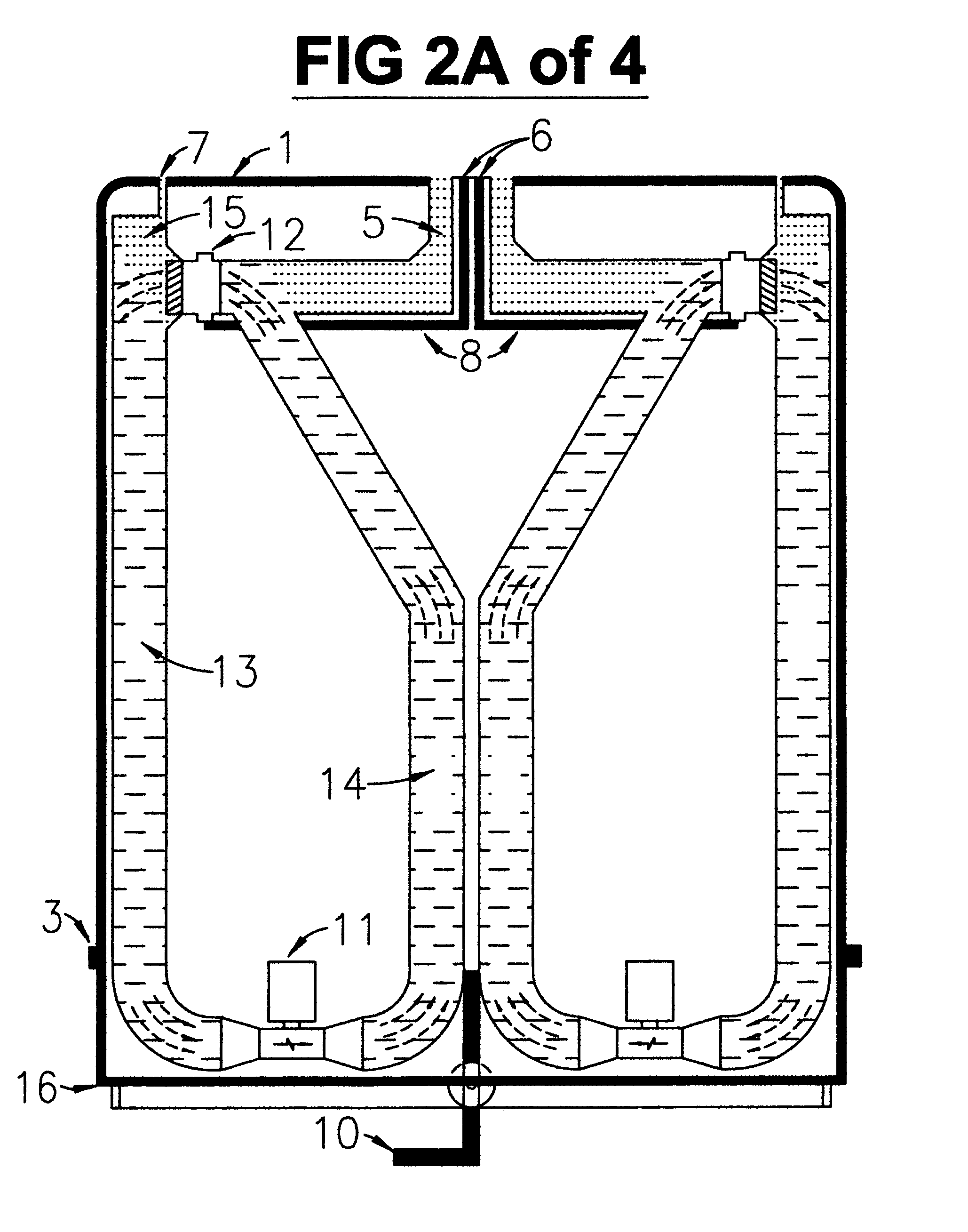
[0013]For purposes of clarity, specific terms are used in the following description of the drawings but are not intended to define or limit the possible types of materials to be used or the location of components within the embodiment or limit the scope of the invention. In addition, the drawings are not to scale but provide a general relationship between the height and width of the apparatus and the relative location of the components within.

[0014]With reference to the drawings, FIG. 1, a cover shield (1) envelopes the entire assembly to reduce air resistance during rotation. The rotor component of a linear synchronous motor (2) is installed on the outer circumference of the cover shield positioned in alignment with the ground mounted stator component (3) of the motor encircling the system. The entire rotating apparatus is mounted upon a system of wear resistant, low friction bearings (4). At the top of the cover shield is the center mounted fill tube (5) for adding water. In the m...


PUM


Abstract

The disclosed invention is a description of the means to create a condition in which liquid matter (water as shown) is subjected to centrifugal force induced by rotating the water as it is circulated in a confined system at velocities sufficient to generate electrical power. The power generated by the system is used to maintain rotation of the entire system, continuously circulate the water within the rotating system and to deliver the surplus electrical energy for discretionary use.

Description

BACKGROUND OF THE INVENTION[0001]1. Technical Field[0002]The present invention relates to creating and efficiently sustaining a condition in which a liquid mass such as water is subjected to centrifugal force while under rotation and to harness the force of the water for purposes of generating electrical energy.[0003]2. Background Art[0004]There have been previous attempts to harness the rotational kinetic energy in mass due to the effects of centrifugal force that result during the circular movement of mass around a fixed axis. All previous attempts to harness this effect have failed due to the laws expressed in the conservation of angular momentum theorem. Accordingly, the energy required to accelerate mass as it moves outwardly from the center of rotation is exactly equal to the potential rotational kinetic energy available in the mass once it reaches an outer orbit. As a result, under previous models, no energy could be extracted from the system without reducing the angular mome...

Claims


Application Information

Patent Timeline
Patent Type & Authority Applications(United States)
IPC IPC(8): F03B7/00H02K53/00
CPCY02E10/20F03B17/005
Inventor HEISS, JOHN CHARLES
Owner HEISS JOHN CHARLES
Why Eureka
Try Eureka