Gravity and buoyancy engine

a buoyancy engine and gravity technology, applied in the field of engines, can solve the problems of neurological damage, air and water pollution emitted by coal and natural gas plants, and the link between breathing problems and oxygen pollution, and achieve the effect of promoting clean energy and significant public health benefits

Active Publication Date: 2020-03-10
FILLORAMO CHRISTOPHER MICHAEL
View PDF9 Cites 2 Cited by
  • Summary
  • Abstract
  • Description
  • Claims
  • Application Information

AI Technical Summary

Benefits of technology

[0003]The purpose of the Gravity & Buoyancy Engine is to produce clean energy. Generating electricity from renewable energy rather than fossil fuels offers significant public health benefits.
[0004]The air and water pollution emitted by coal and natural gas plants is linked to breathing problems, neurological damage, heart attacks, and cancer. The Gravity & Buoyancy Engine is a simple process to create grid distributable electricity with very minimal disruption to our environment and it's economical. By using a heavy buoyant object, gravity and buoyancy as specified in this invention we can replace existing fossil fueled and nuclear power plants.
[0006]In this invention is a tandem dual link chain assembly which will support the cylindrical buoyant object from both ends and will rotate electricity alternators thus creating electricity while the buoyant objects descend by use of gravity. There are physical levers operated during this descending buoyant object which release other buoyant objects into the cycle to constantly energize the tandem dual link chain assembly into creating electricity with the electric alternators.

Problems solved by technology

The air and water pollution emitted by coal and natural gas plants is linked to breathing problems, neurological damage, heart attacks, and cancer.

Method used


Image

  • Gravity and buoyancy engine
  • Gravity and buoyancy engine
  • Gravity and buoyancy engine

Examples


Embodiment Construction

[0013]While described herein are several embodiments of the present invention in sufficient detail so that any person of ordinary skill in the pertinent art, science, or area could construct and practice the invention, it should be understood that mechanical, structural, electrical, logical and operational changes may be made without departing from the spirit and or scope of the invention.

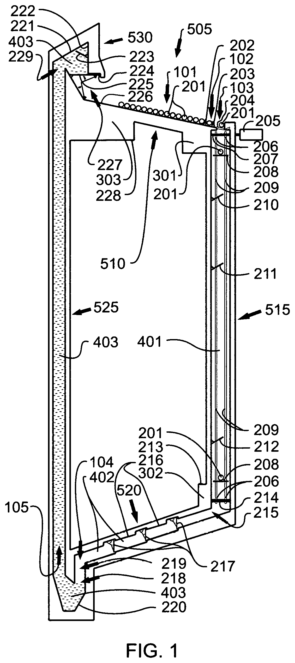
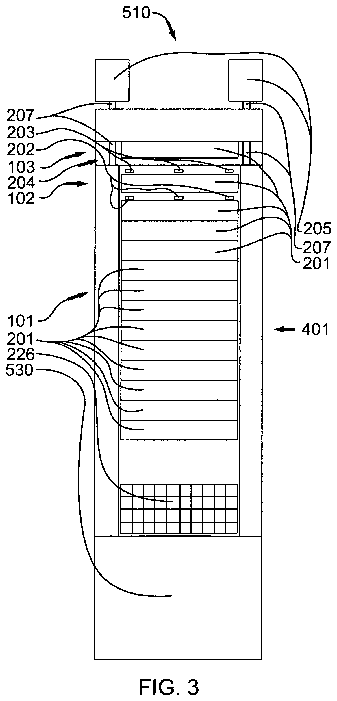
[0014]FIG. 1 illustrates a preferred embodiment of the invention, which is an apparatus (505) with an electricity producing device (205). The apparatus comprises a buoyant objects staging area (510), a gravity chamber (515), a airlock chamber (520), a buoyancy chamber (525), and, a buoyancy exit chamber (530), each of which is now further explained.

[0015]As illustrated in FIG. 1, FIG. 3, the apparatus (505) includes a buoyant objects staging area (510) at normal air pressure (401), for the staging of a plurality of cylindrical buoyant object / s (201) each being of cylindrical shape with a specific g...


PUM


Abstract

A gravity and buoyancy engine has a gravity chamber, an air lock chamber, a buoyancy chamber, an electricity producing device and a cylindrical buoyant object. The air lock chamber is in communication in between the gravity chamber and the buoyancy chamber. The gravity chamber is filled with air at normal pressure. The air lock chamber is filled with air at increased pressure. The buoyancy chamber is filled with fluid. The cylindrical buoyant object is used to move along the gravity chamber via gravity, along the air lock chamber via gravity and along the buoyancy chamber via buoyancy, such that the electricity producing device is able to generate electricity.

Description

FIELD OF THE INVENTION[0001]The present invention generally relates to an engine. More specifically, the present invention relates to a gravity and buoyancy engine.BACKGROUND OF THE INVENTION[0002]The majority of electrical energy humans use pollute the environment through the creation of said electrical energy. Most electrical energy for distribution on power grids is created by burning coal, natural gas, other fuels and use of nuclear power plants. The coal, natural gas and other fuels pollute the environment during the creation of electrical energy. Nuclear power plants pollute the environment when errors, miscalculations and catastrophe's occur during the creation of electrical energy. There are currently renewable energy sources being used in the creation of electrical power but all have their limitations. Limitation include wind not moving, sun not shining and also battery limitations.SUMMARY OF THE INVENTION[0003]The purpose of the Gravity & Buoyancy Engine is to produce clea...

Claims


Application Information

Patent Timeline
Patent Type & Authority Patents(United States)
IPC IPC(8): F03G3/00F03B17/04H02K53/00H02K7/18F03G7/10
CPCH02K7/1853F03B17/04H02K53/00F03G3/00Y02E10/20Y10S74/09F03G7/10F03G7/104
Inventor FILLORAMO, CHRISTOPHER MICHAEL
Owner FILLORAMO CHRISTOPHER MICHAEL
Why Eureka
Try Eureka