Optical inclinometer

An inclinometer and optical technology, applied in the field of optical inclinometers, can solve the problems of not considering the exact position of the light-dark transition of the detector, roughly estimating the inclination, shrinking the volume, etc.

Inactive Publication Date: 2005-08-24
LEICA GEOSYSTEMS AG
View PDF3 Cites 9 Cited by
  • Summary
  • Abstract
  • Description
  • Claims
  • Application Information

AI Technical Summary

Problems solved by technology

Due to this structure, it is not possible to utilize any information about the dimming of the photodiode by shadow casting
In particular no consideration is given to the exact position of the light-dark transition on the detector
[0008] Therefore, in the prior art, although high-precision and well-developed inclinometers are kn

Method used


Image

  • Optical inclinometer
  • Optical inclinometer
  • Optical inclinometer

Examples


Embodiment Construction

[0043] The method according to the invention or the device according to the invention will be explained in more detail below purely by way of example on the basis of the exemplary embodiments shown schematically in the figures.

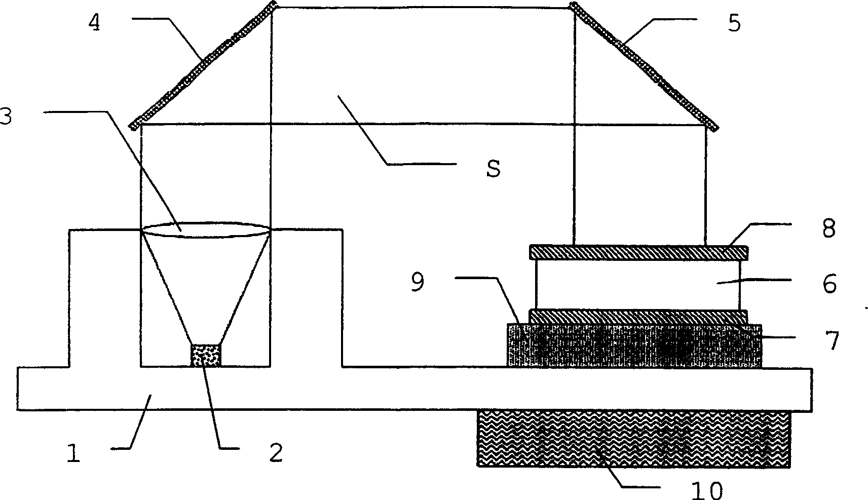
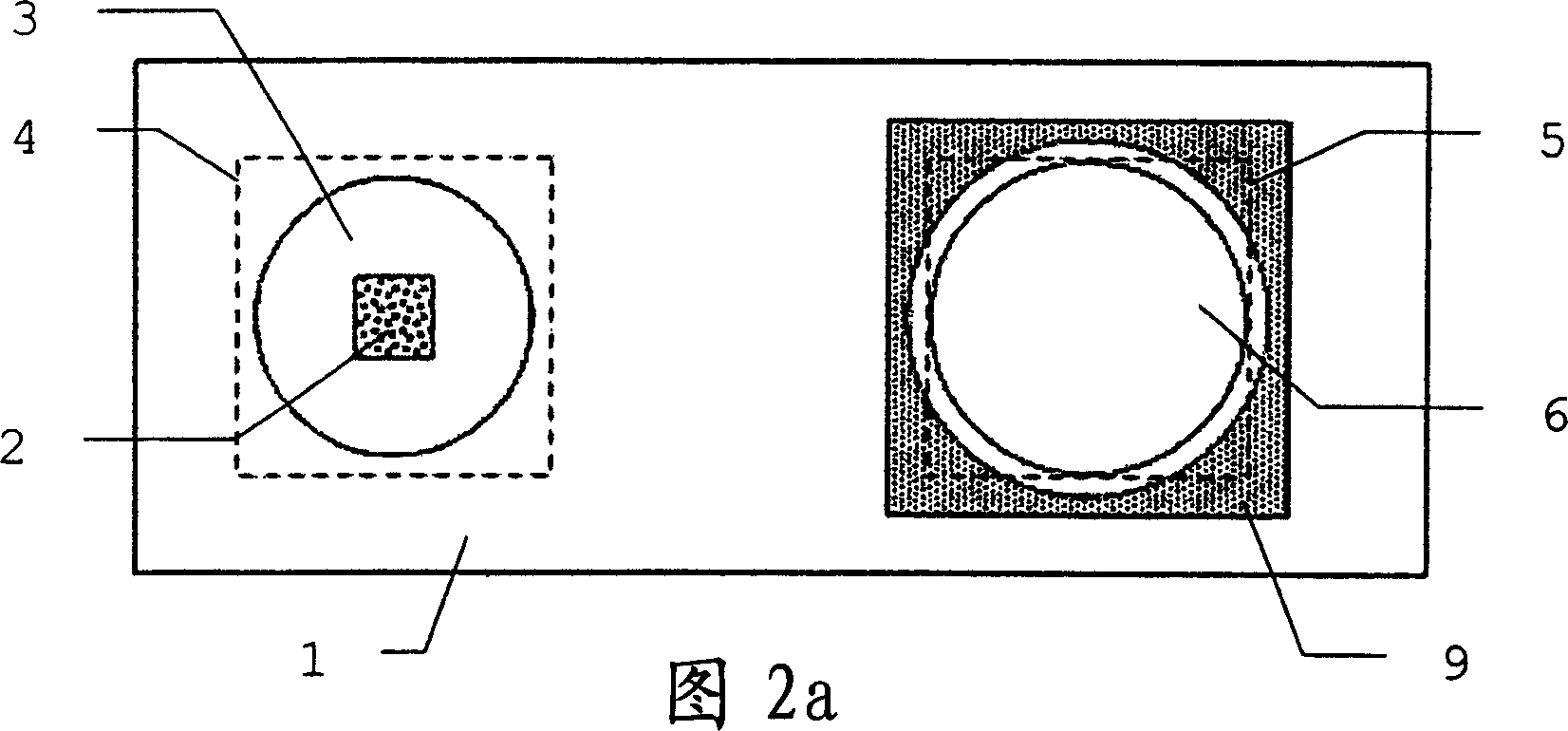
[0044] figure 1 A side view of a first embodiment of an optical inclinometer according to the invention with all components integrated on a board as a common base 1 is schematically shown. Visible or invisible radiation S is emitted by the radiation source 2 perpendicular to the susceptor 1 . The radiation S is collimated by the lens 3 and deflected again by the first deflection element 4 and the second deflection element 5 such that it is perpendicularly incident on the susceptor 1 . In the region of this incident radiation, a receiving element 6 is mounted on the base 1 , having a first surface 7 oriented towards the base and a second surface 8 oriented towards the second deflection element. Between the base 1 and the receiving element or its firs...


PUM


Abstract

The invention relates to an optical inclinometer, in which radiation (S) is emitted from a radiation source (2). After passing through a receptacle (6, 6') containing at least one first medium (11, 13), said radiation (S) is reproduced in a camera (9). Information concerning the inclination of the inclinometer can be gathered from the position of the first medium (11, 13), in particular a liquid level, in relation to the inclinometer or the camera (9). The recording of the position of the first medium (11, 13) by a camera (9) permits the evaluation of a plurality of characteristics, in particular the form, dimension and position of a boundary layer (14).

Description

technical field [0001] The invention relates to an optical inclinometer according to the preamble of claim 1 , a method for measuring the inclination of an instrument according to the preamble of claim 17 and a geodetic instrument having such an inclinometer. Background technique [0002] Inclinometers of various construction types have been used for a long time in all fields where the position of the instrument has to be taken into account. This applies in particular to measurements in the field of geodesy or in the construction industry. [0003] Although various implementations with complex structures are known for high-precision measurements, there has hitherto been a lack of simple and robust inclinometers which still have sufficient accuracy. [0004] In US 5,392,112 an inclinometer is described which splits a beam of light into two sub-beams which are focused on a detector and is documented here. The inclination of the instrument is deduced from the relative positi...

Claims


Application Information

Patent Timeline
IPC IPC(8): G01C9/06G01C9/12G01C9/20G01C9/24
CPCG01C9/06G01C9/20G01C2009/066
Inventor 库尔特·埃内库尔特·吉热
Owner LEICA GEOSYSTEMS AG
Why Eureka
Try Eureka