Positioning System For Single Or Multi-Axis Sensitive Instrument Calibration And Calibration System For Use Therewith

a calibration system and sensitive instrument technology, applied in the direction of instruments, calibration apparatus, using mechanical means, etc., can solve the problems of coarse prediction of angular orientation, corresponding deterioration in measurement resolution, and certain weaknesses

Inactive Publication Date: 2008-08-28
NASA
View PDF16 Cites 43 Cited by
  • Summary
  • Abstract
  • Description
  • Claims
  • Application Information

AI Technical Summary

Benefits of technology

[0012]Accordingly, it is an object of the present invention to provide a system that can be used to position a single or multi-axis sensitive instrument for calibration and a calibration system for use therewith.
[0013]Another object of the present invention to provide a system that can be used to position a single or multi-axis sensitive instrument for a simple in-situ calibration procedure.
[0014]Another object of the present invention to provide a system that can be used to position an inertial-based attitude measurement instrument for calibration and a calibration system for use therewith.
[0015]Yet another object of the present invention to provide a system that can be used to position an inertial-based attitude measurement instrument for a simple in-situ calibration procedure.

Problems solved by technology

As the device is moved away from its sensitive attitude, there is a corresponding deterioration in the measurement resolution.
However, in the limiting case, the device's sensitive axis is collinear with the gravitational vector resulting in coarse predictions of angular orientation.
While these systems represent the state-of-the-art in accelerometer calibration, they also possess certain weaknesses.
For example, these systems are costly and are permanently mounted in a laboratory thereby making them incompatible for in-situ calibration.
In addition, they require a complex calibration procedure to partially compensate for the near-levelness of the mounting surface and the orthogonal misalignment among the sequence of rotary tables.

Method used


Image

  • Positioning System For Single Or Multi-Axis Sensitive Instrument Calibration And Calibration System For Use Therewith
  • Positioning System For Single Or Multi-Axis Sensitive Instrument Calibration And Calibration System For Use Therewith
  • Positioning System For Single Or Multi-Axis Sensitive Instrument Calibration And Calibration System For Use Therewith

Examples


Embodiment Construction

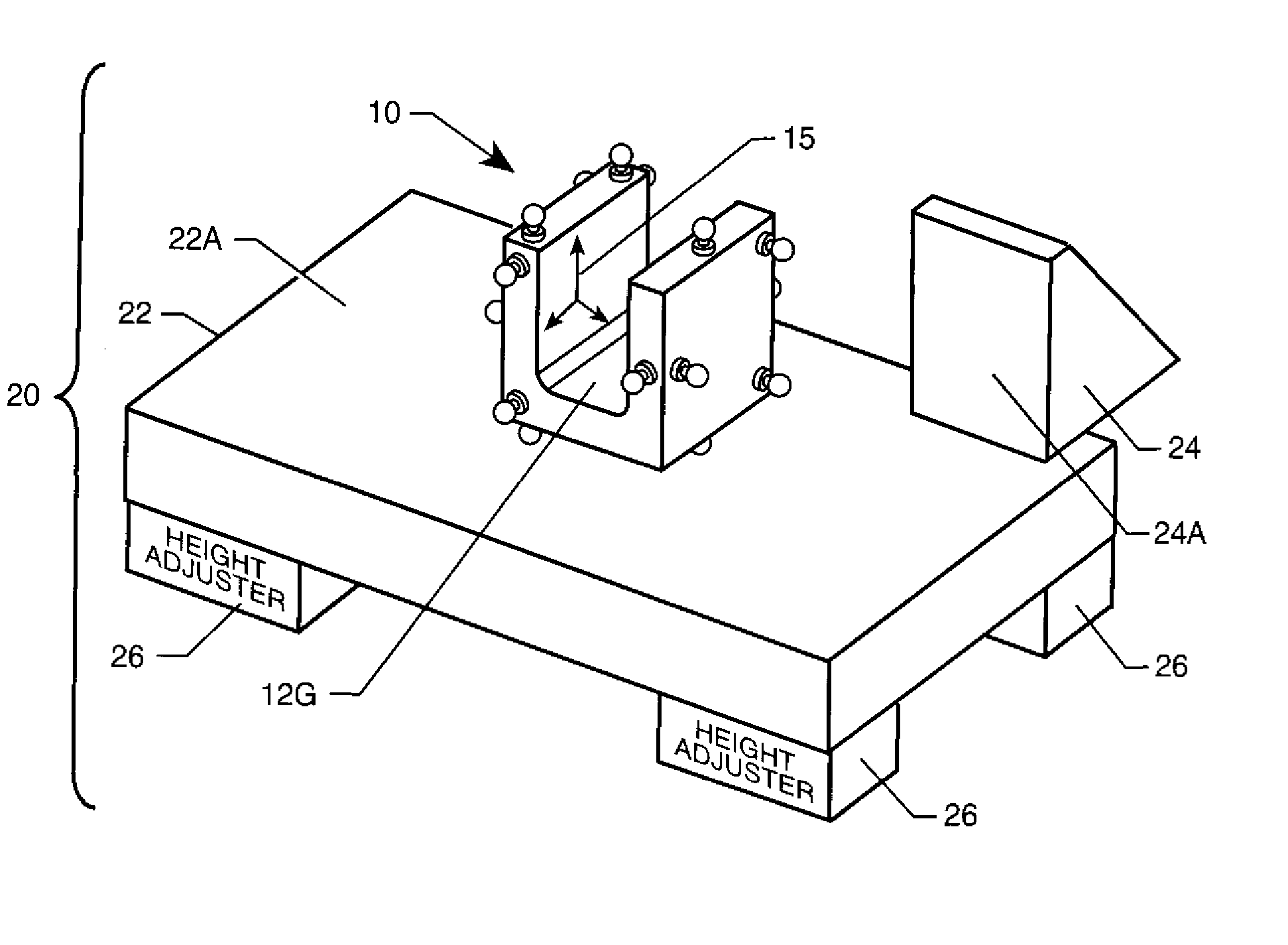
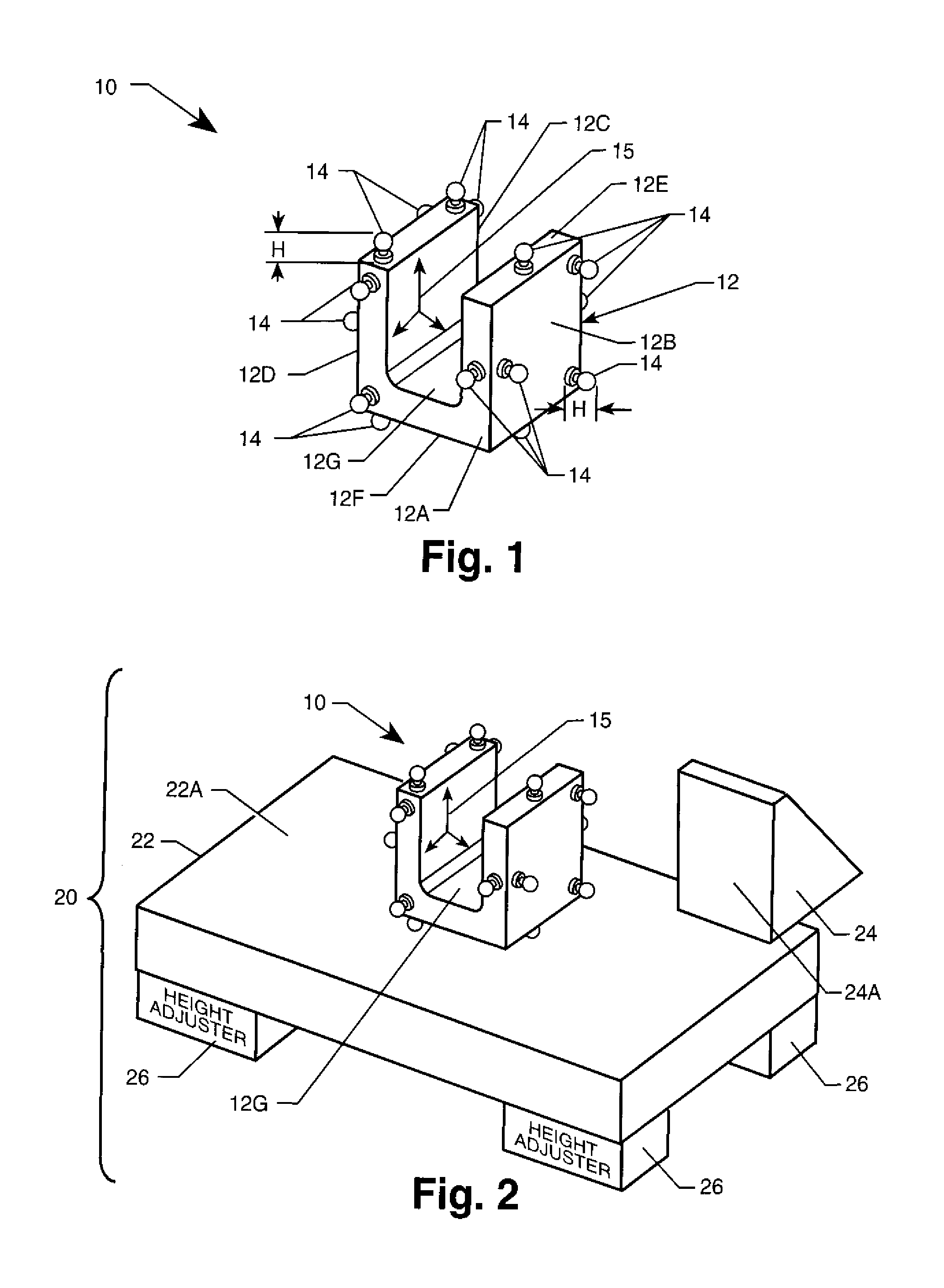
[0027]Referring now to the drawings and more particularly to FIG. 1, a cuboidal frame positioner is shown in isolation and is referenced generally by numeral 10. Cuboidal frame positioner 10 forms the basic structure of the positioning system of the present invention. More specifically, cuboidal frame positioner 10 can support a single or multi-axis inclinometer such as an accelerometer (not shown) that is to be positioned for calibration in accordance with the teachings of the present invention. As stated above, as will be readily apparent to one of ordinary skill in the art, the type of axis sensitive instrument being positioned / calibrated (an inclinometer), is not a limitation of the present invention, nor is the type of inclinometer referenced. However, by way of illustrative example, the remainder of the description will make reference to the positioning / calibration of a tri-axial accelerometer having three mutually orthogonal axes of sensitivity. Such devices are well-known an...


PUM


Abstract

A positioning and calibration system are provided for use in calibrating a single or multi axis sensitive instrument, such as an inclinometer. The positioning system includes a positioner that defines six planes of tangential contact. A mounting region within the six planes is adapted to have an inclinometer coupled thereto. The positioning system also includes means for defining first and second flat surfaces that are approximately perpendicular to one another with the first surface adapted to be oriented relative to a local or induced reference field of interest to the instrument being calibrated, such as a gravitational vector. The positioner is positioned such that one of its six planes tangentially rests on the first flat surface and another of its six planes tangentially contacts the second flat surface. A calibration system is formed when the positioning system is used with a data collector and processor.

Description

ORIGIN OF THE INVENTION[0001]Pursuant to 35 U.S.C. §119, the benefit of priority from provisional application 60 / 740,292, with a filing date of Nov. 21, 2005, is claimed for this non-provisional application.[0002]This invention was made in part by employees of the United States Government and may be manufactured and used by or for the Government of the United States of America for governmental purposes without the payment of any royalties thereon or therefor.BACKGROUND OF THE INVENTION[0003]1. Field of the Invention[0004]This invention relates to the calibration of single or multi-axis sensitive instruments, such as an inertial-based attitude measurement instruments or inclinometers. More specifically, the invention is a positioning system used for single or multi-axis sensitive instrument calibration and a calibration system that can be used with the positioning system.[0005]2. Description of the Related Art[0006]Many well-known single or multi-axis sensitive instruments, which whe...

Claims


Application Information

Patent Timeline
Patent Type & Authority Applications(United States)
IPC IPC(8): G01C25/00
CPCG01C25/005G01P21/00
Inventor FINLEY, TOM D.PARKER, PETER A.
Owner NASA
Why Eureka
Try Eureka